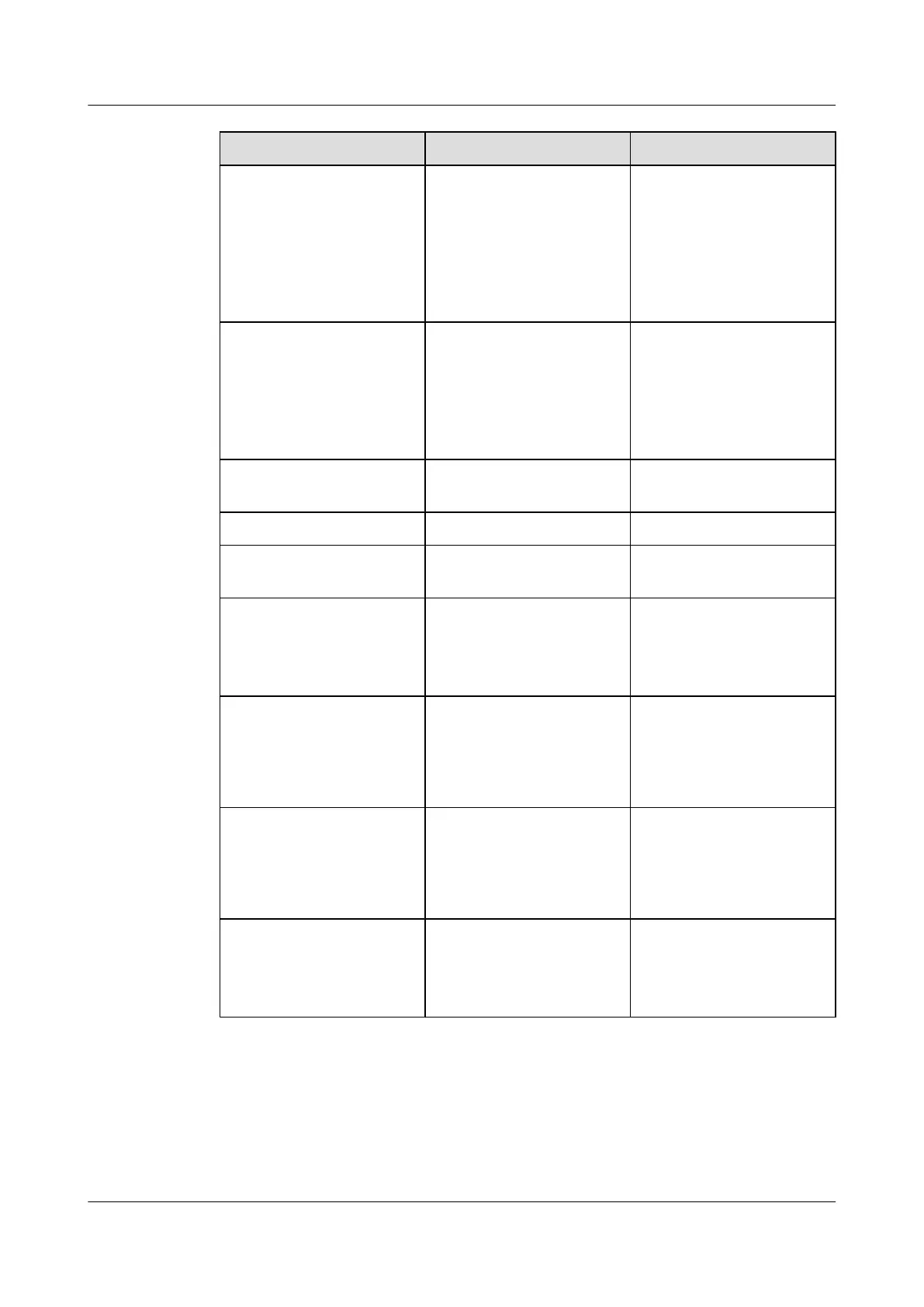
Silk Screen Function Remarks
JTA1-JTA3 Socket for the standby analog
signal output/input
l Connected to the external
sensor, and outputting the
4-20 mA current or the
0-5 V voltage
l Selecting the type of the
accessed signals through
the DIP switches
JTA4-JTA6
Socket for the standby analog
signal output/input
l Connected to the external
sensor, and outputs the
4-20 mA current or the
0-5 V voltage
l Connected to the analog
sensors
FAN
Socket for fan control Connected to the power port
on the controlled fan
BGND, -48 V Power input Connected to the DC busbar
GND Communication ground Connected to the working
ground of the control board
RSP/PV8 Communicating with the
upper-layer device through
the active communication
port in the RS-232 mode
l RJ45 port
l Connected to the
communication port on
the active control board
SIO2 Communicating with the
upper-layer device through
the active communication
port in the RS-232 or RS-422
mode
l RJ45 port
l Connected to the
communication port on
the standby control board
SIO1 Communicating with the
power supply device through
the active communication
port in the RS-232 or RS-422
mode
l RJ45 port
l Connected to the
supported primary power
supply device
SIO3 Transparent transmission
port; working in the RS-232
or RS-422 mode
l RJ45 port
l Connected to the device
that requires transparent
transmission
Jumper and DIP Switch
The H303ESC board resides in the right of the EMU and provides two DIP switches: S6 and
S7, and six jumpers: S1, S2, S3, S8, S10, and S11, as shown in Figure 3-3.
UA5000 Universal Access Unit
Environment Monitoring 3 H303ESC Monitoring Solution
Issue 01 (2012-08-17) Huawei Proprietary and Confidential
Copyright © Huawei Technologies Co., Ltd.
9
 Loading...