Replacement
Replace in reverse order.
Attention: To prevent damage to cards in the drawer, refer to drawing on “10 EIA-Unit
I/O Drawer Cable Routing” on page 42, and ensure the cables are routed correctly.
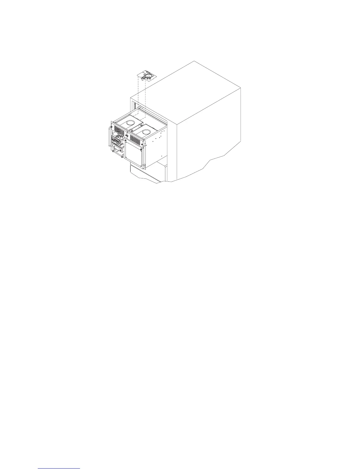
Service Processor Card
Before performing these procedures, read “Safety Notices” on page xiii.
Removal
1. If possible, record the customer’s settings for bootlist, modem configuration, call-in,
call-out, and so on.
2. Perform the procedure in “Powering Off the System” on page 492.
3. Open the I/O rack doors.
4. Do the steps in “I/O Tray” on page 513 that allow you to move the I/O tray a few
inches to the rear. Leave the internal cables connected to the I/O planar and
installed adapters.
5. The service processor is in slot 8 of the primary I/O drawer.
530 Service Guide
 Loading...