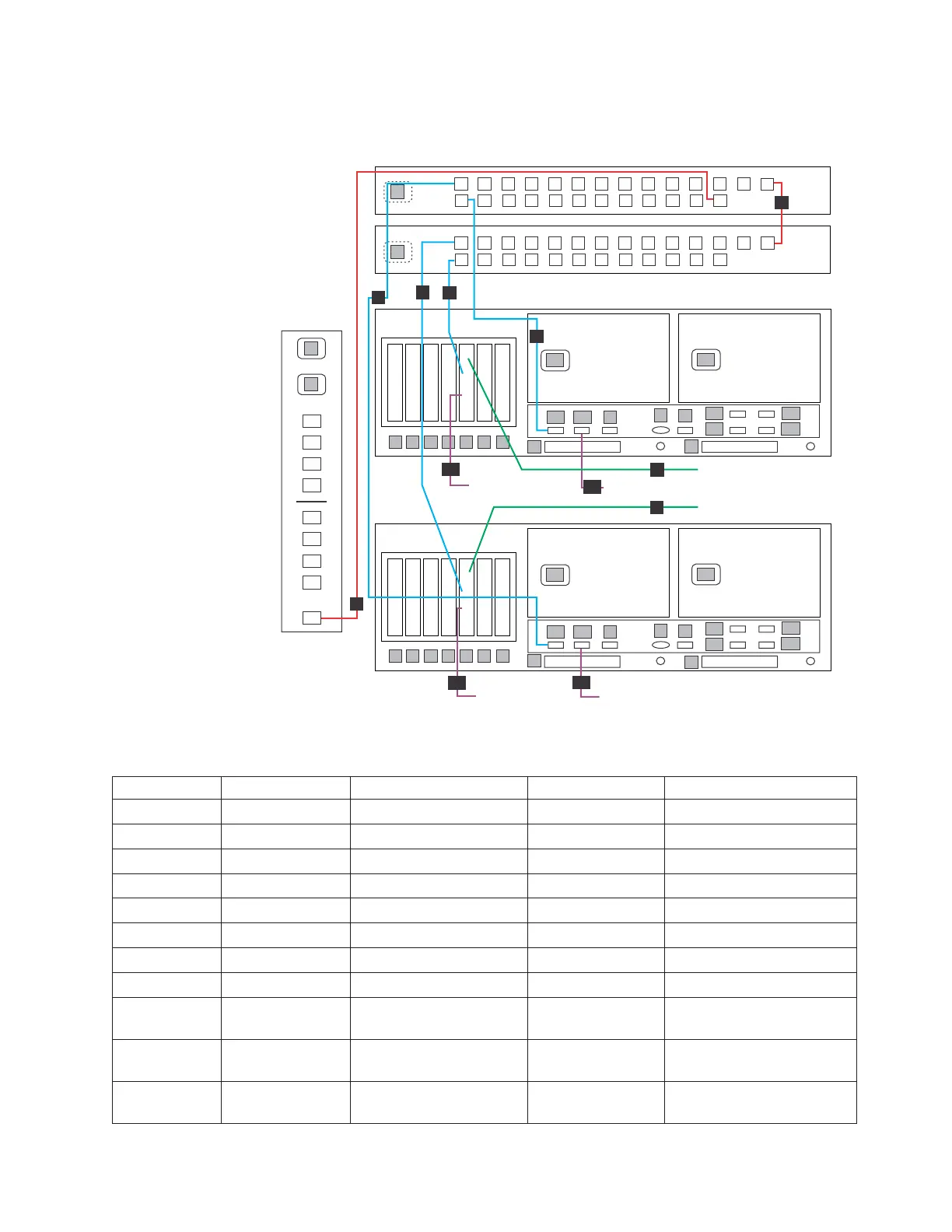
cables according to the port number assignments specified in Table 21, regardless
of the position of the ports on the TSSC or the switch.
Table 21. Clustered 1-Gb Ethernet switch Ethernet connections for VTL configuration
Callout From On Device To On Device/Location
1 Slot 5, port 1 Server A Customer network Customer designated device
2 Port 1 Ethernet switch 1 Slot 5, port 2 Server A
3 Port 1 Ethernet switch 2 Port A1 Server A
4 Port 3 Ethernet switch 2 Ethernet port, E WTI network power switch
5 Port 4 Ethernet switch 2 Port 4 Ethernet switch 1
6 Slot 5, port 1 Server B Customer network Customer designated device
7 Port 2 Ethernet switch 1 Slot 5, port 2 Server B
8 Port 2 Ethernet switch 2 Port A1 Server B
19 Slot 5, port 3 Server A Customer
replication network
Customer specified device
20 Port A2 Server A Customer
replication network
Customer specified device
26 Slot 5, port 3 Server B Customer
replication network
Customer specified device
WTI
network
power switch
Ethernet switch 2
Ethernet switch 1
ProtecTIER Server B
1
2
11
1
222
1
2
3
4
5
6
7
E1
E2
1
3
2
4
P1
P2
8
A1
A2
9
B
V
E3
E4
S
ProtecTIER Server A
1
1
22
1
3
2
4
9
10
11
12
13
14
15
16
1
2
3
4
5
6
7
8
19
20
21
22
23
24
25
17
18
9
10
11
12
13
14
15
16
1
2
3
4
5
6
7
8
19
20
21
22
23
24
25
17
18
2
8
5
Replication 2
27
Replication 1
Customer Network
Customer Network
1
Replication 2
20
Replication 1
ts760862
P1
P2
1
2
3
4
5
6
7
8
A1
A2
B
E1
E2
V
S
9
E3
E4
P
P
P
P
A1
A2
A3
A4
B1
B2
B3
B4
E
3
4
1
2
1
2
7
6
26
19
26
26
Figure 30. Clustered 1-Gb Ethernet switch connections for VTL configuration
Chapter 3. Installing the appliance 51
 Loading...