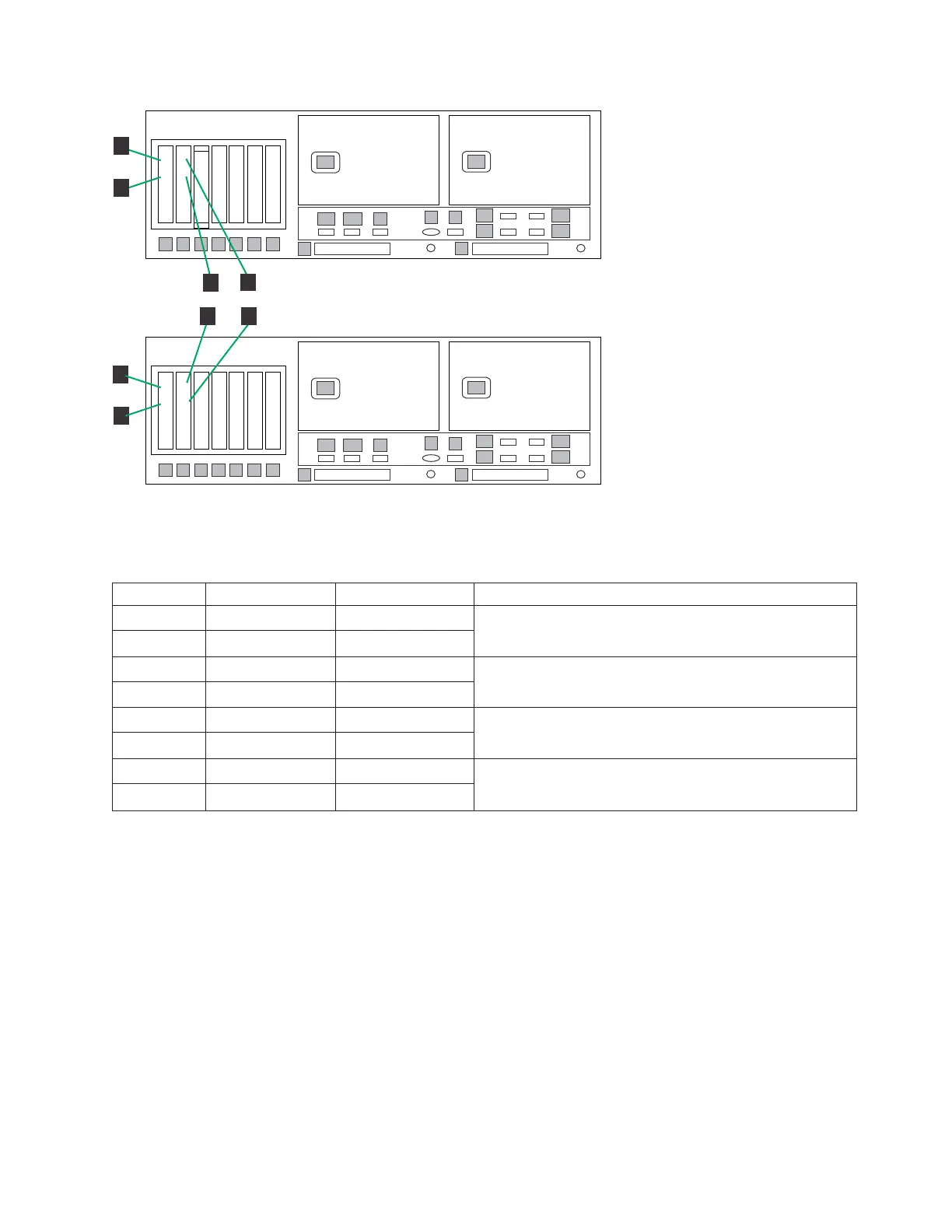
Table 27. Clustered Host Fibre Channel labels
Label From To Remarks
1 DD4A S1 1 HOST 1
v Label port 1 = Fibre Channel port 2
v Label port 2 = Fibre Channel port 3
2 DD4A S1 2 HOST 2
3 DD4A S2 1 HOST 3
v Label port 1 = Fibre Channel port 0
v Label port 2 = Fibre Channel port 1
4 DD4A S2 2 HOST 4
5 DD4B S1 1 HOST 1
v Label port 1 = Fibre Channel port 2
v Label port 2 = Fibre Channel port 3
6 DD4B S1 2 HOST 2
7 DD4B S2 1 HOST 3
v Label port 1 = Fibre Channel port 0
v Label port 2 = Fibre Channel port 1
8 DD4B S2 2 HOST 4
Procedure
Perform the following steps to verify VTL Fibre Channel connections.
1. Connect the Fibre Channel cables to the customer host network according to
Table 26 on page 62 and Figure 36 on page 61.
Note: The customer must use an additional connectivity device between the
optical Fibre directly connected to RMSS optical adapters (for example, Fibre,
ESCON, or FICON) and an external public network. It can be a patch panel,
router, switch, or other suitable device. Optical Fibre connectivity that does not
go over a public network does not require an additional connectivity device.
2. Use Figure 36 on page 61 to verify the Fibre Channel connections made in
manufacturing.
3. Make any necessary adjustments to cable labeling or placement, then go to
“Powering up the components” on page 68.
ts760930
1
1
22
1
2
3
4
5
6
7
E1
E2
1
3
2
4
P1
P2
8
A1
A2
9
B
V
E3
E4
S
ProtecTIER Server B
1
1
22
1
2
3
4
5
6
7
E1
E2
1
3
2
4
P1
P2
8
A1
A2
9
B
V
E3
E4
S
1
2
ProtecTIER Server A
1
2
1
2
1
2
1
2
5
6
3
4
7
8
Figure 37. Clustered Host Fibre Channel labels
Chapter 3. Installing the appliance 63
 Loading...