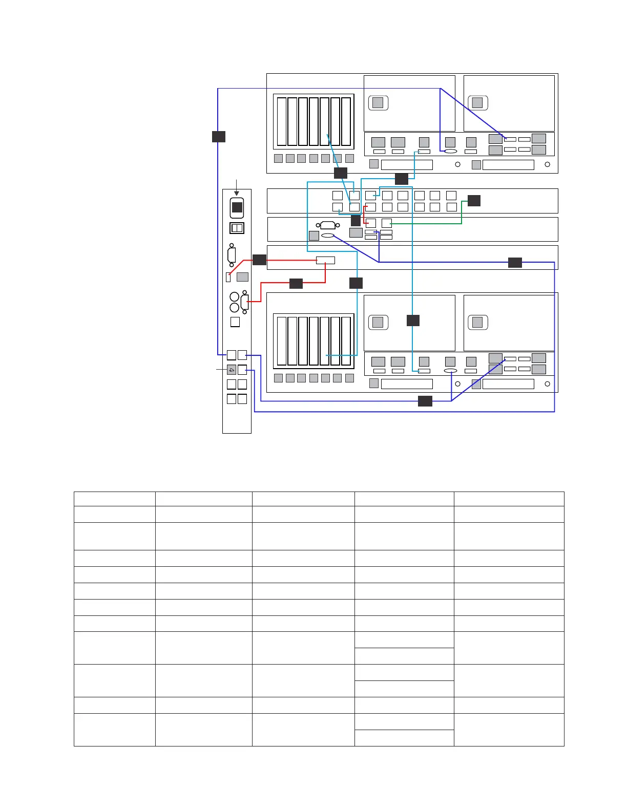
Table 24. Clustered TSSC, KVM, and customer network Ethernet connections
Callout From On Device To On Device/Location
9 Port 5 TSSC Ethernet switch Port 1 TSSC
10 Port 2 TSSC Customer local area
network
Customer specified
device
11 Port 4 TSSC Ethernet switch Slot 5, port 4 Server A
12 Port 3 TSSC Ethernet switch Slot 5, port 4 Server B
13 Port 6 TSSC Ethernet switch Port B (IMM) Server A
14 Port 1 TSSC Ethernet switch Port B (IMM) Server B
21 Video port KVM Switch Video port SC KVM
22 Port 3 KVM Switch Video port, SC Server
Port U3
23 Port 1 KVM Switch Video port, Server A
Port E1
24 Port U1 KVM Switch Video Port SC KVM
25 Port 2 KVM Switch Video port, Server B
Port E1
1
2
3
4
5
6
7
8
9
10
13
12
11
14
15
16
U1
8
9
A1 A2 B V S
E1
E2
E3
E4
23
21
24
11
8
9
A1 A2 B V S
E1
E2
E3
E4
14
12
25
1
2
V
U3
9
13
10
22
KVM
switch
1
2
3
4
5
6
7
8
Terminator
P
SC SW
SC KVM
1
2
1
2
1
2
1
2
ProtecTIER Server A
1
2
34567
1
2
3
4
PP
Customer
Network
ts760989
1
2
1
2
1
2
1
2
ProtecTIER Server B
1
2
34567
1
2
3
4
PP
SC Server
Figure 34. Clustered TSSC, KVM, and customer network Ethernet connections, TSSC variant
2
Chapter 3. Installing the appliance 57
 Loading...