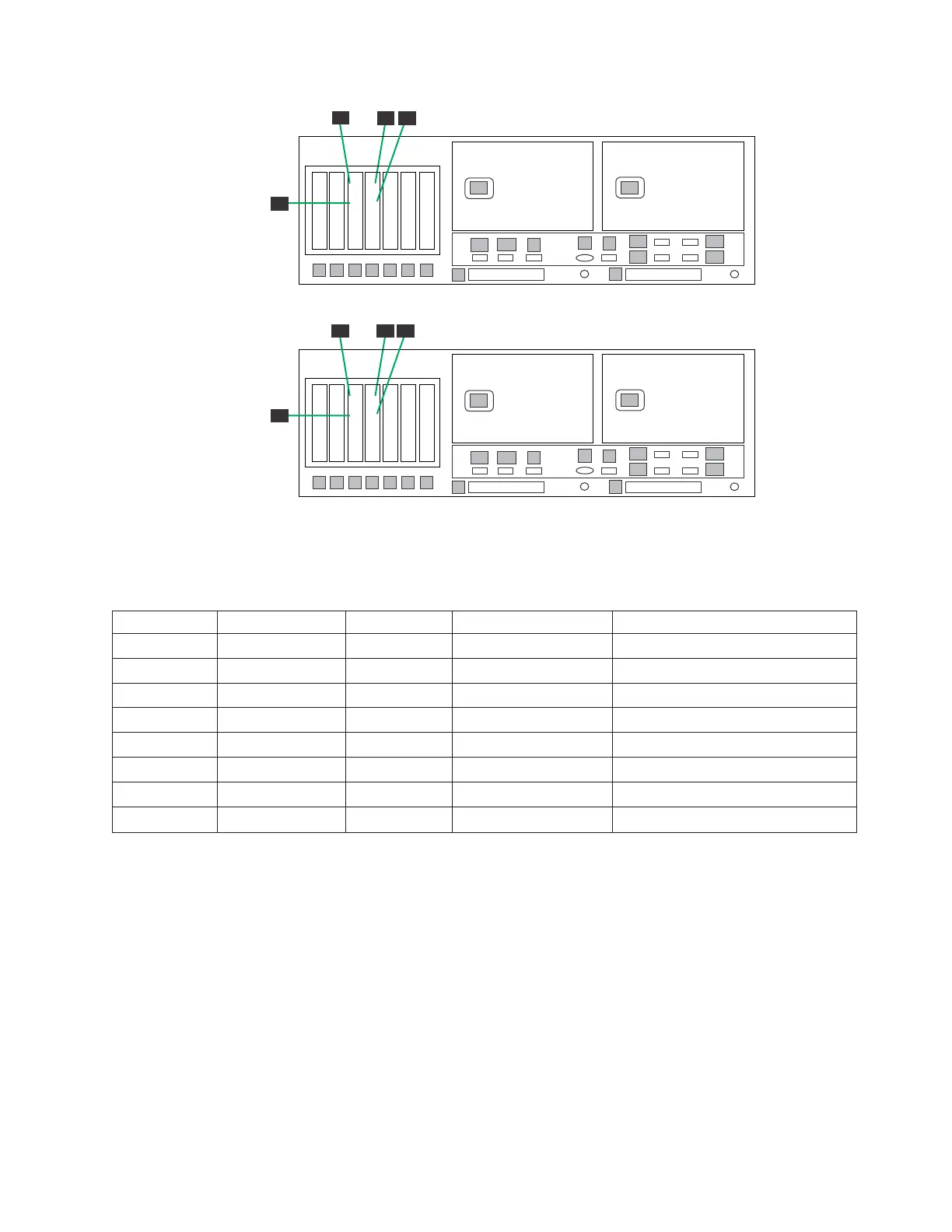
Table 29. Clustered Ethernet host connections for OpenStorage configuration, Feature Code 3457
Callout From On Device To On Device/Location
13 Slot 3, port 1 Server A Designated device Customer host network
14 Slot 3, port 2 Server A Designated device Customer host network
15 Slot 4, port 1 Server A Designated device Customer host network
16 Slot 4, port 2 Server A Designated device Customer host network
17 Slot 3, port 1 Server B Designated device Customer host network
18 Slot 3, port 2 Server B Designated device Customer host network
19 Slot 4, port 1 Server B Designated device Customer host network
20 Slot 4, port 2 Server B Designated device Customer host network
Procedure
Perform the following steps to verify OpenStorage Fibre Channel connections.
1. Use Figure 38 on page 65 and Table 28 on page 66 to verify the Fibre Channel
connections made in manufacturing.
2. Connect the Fibre Channel cables to the customer host network according to
Figure 39 and Table 29.
Note: The customer must use an additional connectivity device between the
optical Fibre directly connected to RMSS optical adapters (for example, Fibre,
ESCON, or FICON) and an external public network. It can be a patch panel,
router, switch, or other suitable device. Optical Fibre connectivity that does not
go over a public network does not require an additional connectivity device.
ts760867
1
1
22
1
2
3
4
5
6
7
E1
E2
1
3
2
4
P1
P2
8
A1
A2
9
B
V
E3
E4
S
1
2
1
2
ProtecTIER Server B
1
1
22
1
2
3
4
5
6
7
E1
E2
1
3
2
4
P1
P2
8
A1
A2
9
B
V
E3
E4
S
1
2
1
2
18
14
17
19
20
13
15
16
ProtecTIER Server A
Figure 39. Clustered customer host network Ethernet connections for OpenStorage
configuration, Feature Code 3457
Chapter 3. Installing the appliance 67
 Loading...