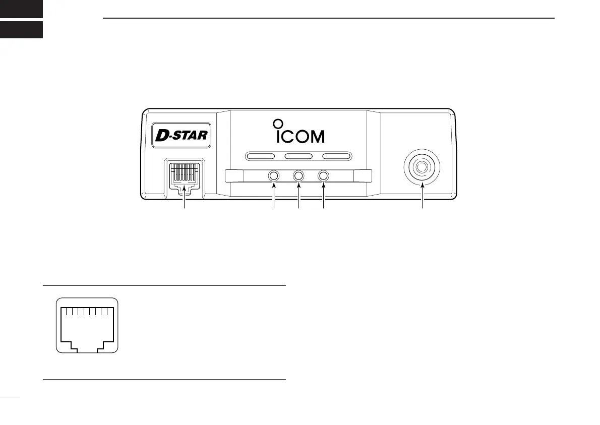
■ Front panel
qMICROPHONE CONNECTOR [MIC]
Connects the supplied microphone or the remote con-
troller, RC-24 (optional for some versions).
q +8 V DC output (Max. 100 mA)
w Channel up/down
e Data out
r PTT
t GND (microphone ground)
y MIC (microphone input)
u GND
i Data IN
wDATA TRANSMIT/RECEIVE INDICATOR
Lights green while receiving; lights red while transmitting
data in data mode.
ePOWER INDICATOR
Lights while the transceiver power is turned ON.
rTRANSMIT/RECEIVE INDICATOR
Lights green while receiving; lights red while transmitting
in FM/digital voice mode.
tPOWER SWITCH [POWER]
Turns power ON and OFF when pushed for 1 sec.
MIC
TD/RD PWR TX/RX
POWER
TRANSCEIVER
ID-1
DIGITAL
qewr t
1
PANEL DESCRIPTION
New2001
1
ID-1_ENG_2.qxd 04.9.22 9:29 Page 1 (1,1)

 Loading...


