EN
EN-24 80447162 Rev B
Option
Items
Selection Min. Max. Step Unit Installed
option
required?
Remote
Start-
Stop
ON/OFF --- --- --- --- No
Enable
PORO
ON/OFF --- --- --- --- Yes
PORO
Time
--- 10 600 1 Sec Yes
--- Day Day 1 Day Yes
--- 00:00 23:59 1 Time Yes
--- Day Day 1 Day Yes
--- 00:00 23:59 1 Time Yes
Modbus
Protocol
ON/OFF/
ICU
--- --- --- --- No
Modbus
Address
--- 1 247 1 --- No
If an option has not been purchased and installed in the compressor, the
message “Not Installed” will be shown on the selection display screen.
Installation of options will be done using the Ingersoll Rand service tool.
* The low ambient temperature is only adjustable if the low ambient factory
set point is ON.
** A value of 0 will disable the lead/lag cycle time feature.
Pages 6-7: Sensor Calibration
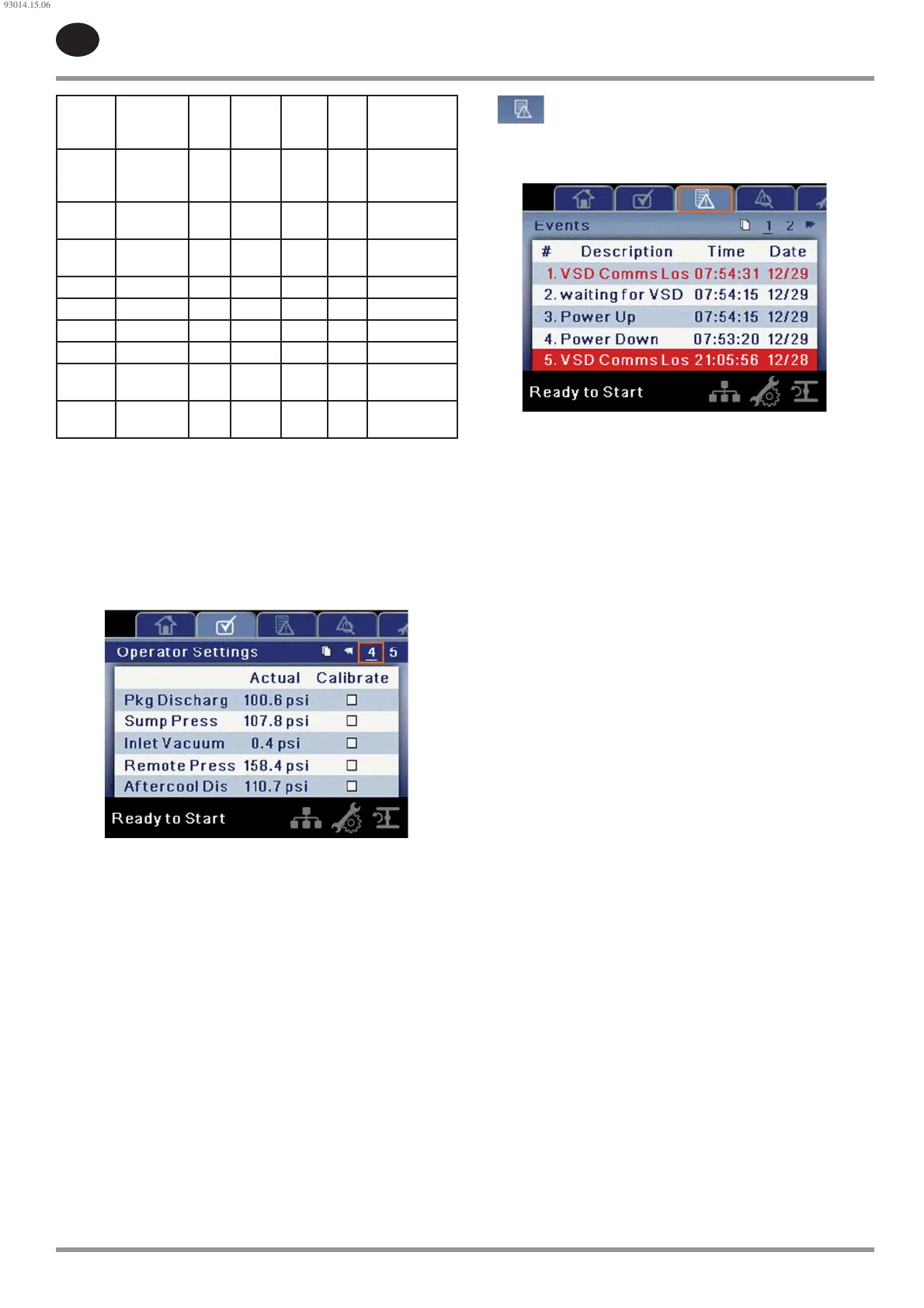
Figure 42 : Sensor Calibration
Sensor calibration can only take place when the compressor is stopped.
There should be no pressure on a sensor when it is calibrated. Calibration
only needs to take place after a sensor is replaced, the controller is replaced,
or the operator suspects the sensor reading is in error. Calibrate a sensor by
selecting the checkbox beside the sensor name.
Each of the sensors listed below can be calibrated.
Inlet Vacuum (1AVPT)
Sump Pressure (3APT)
Package Discharge Pressure (4APT)
Coolant Filter Inlet Pressure (5CPT)
Coolant Filter Outlet Pressure (6CPT)
Remote Pressure (10APT) – Only on compressors with the remote sensor
option
Interstage Pressure (2APT) – Only on 2-stage compressors
After-cooler Discharge Pressure (7APT) – Only on compressors with
integrated dryer
Please note that if a sensor is currently reading a value that is +/- 10% of
its range from zero, the sensor will not be able to be calibrated. Please
make sure the sensor is being exposed to atmosphere before attempting
calibration.
•
•
•
•
•
•
•
•
Events folder
Pages 1-42 (max.)
Figure 43 : Events Folder
The pages in the Events folder document up to the last 250 events that the
controller has experienced, and time stamps each. The events are recorded
in sequence, with number one being the newest and 250 being the oldest.
When a new event occurs, it becomes number one and all others are shifted
up in number.
The page numbers in the Title Bar are used to scroll through the events, with
each page displaying up to seven. Page one displays events one through six,
page two displays seven through twelve, and so on.
The following actions will generate an event:
Power ON
Power OFF
Press the Start Key
Press the Stop Key
Press the Load Key
Press the Unload Key
Warning
Trip
Start Inhibit
Active Warnings will be highlighted in amber while cleared Warnings will
have amber text.
Active Trips will be highlighted in red while cleared Trips will have red text.
Active Start Inhibits will be listed in the Event log, but not highlighted. The
display will indicate the compressor is not ready to start if a start inhibit is
active.
See the following lists for details about messages in each type of event.
Warning Events List
Change Inlet Filter
This will occur if the compressor has been running for at least 7 seconds, the
motor speed is equal to or greater than the minimum speed, and the inlet
vacuum is greater than 0.7 psi.
Change Coolant Filter
This will occur if the compressor has been running for at least 7 seconds, the
injected coolant temperature is at least 140 °F, the motor speed is at least
equal to the minimum speed, and the coolant lter pressure drop (5CPT
- 6CPT) is greater than 25 psi.
Sensor Failure (Units without Integrated Dryer)
Will occur whenever a sensor is recognized as missing or broken. The sensors
a ected by this warning are 1ATT, 2ATT, 4ATT, and 3CTT. The sensor failure
message shall follow the following format: SENSOR FAILURE 4ATT.
Sensor Failure (Units with Integrated Dryer)
Will occur whenever a sensor is recognized as missing or broken and the
compressor has an integrated dryer (3.3.1.6). The sensors a ected by this
•
•
•
•
•
•
•
•
•
93014.15.06
 Loading...