EN
EN-34 80447162 Rev B
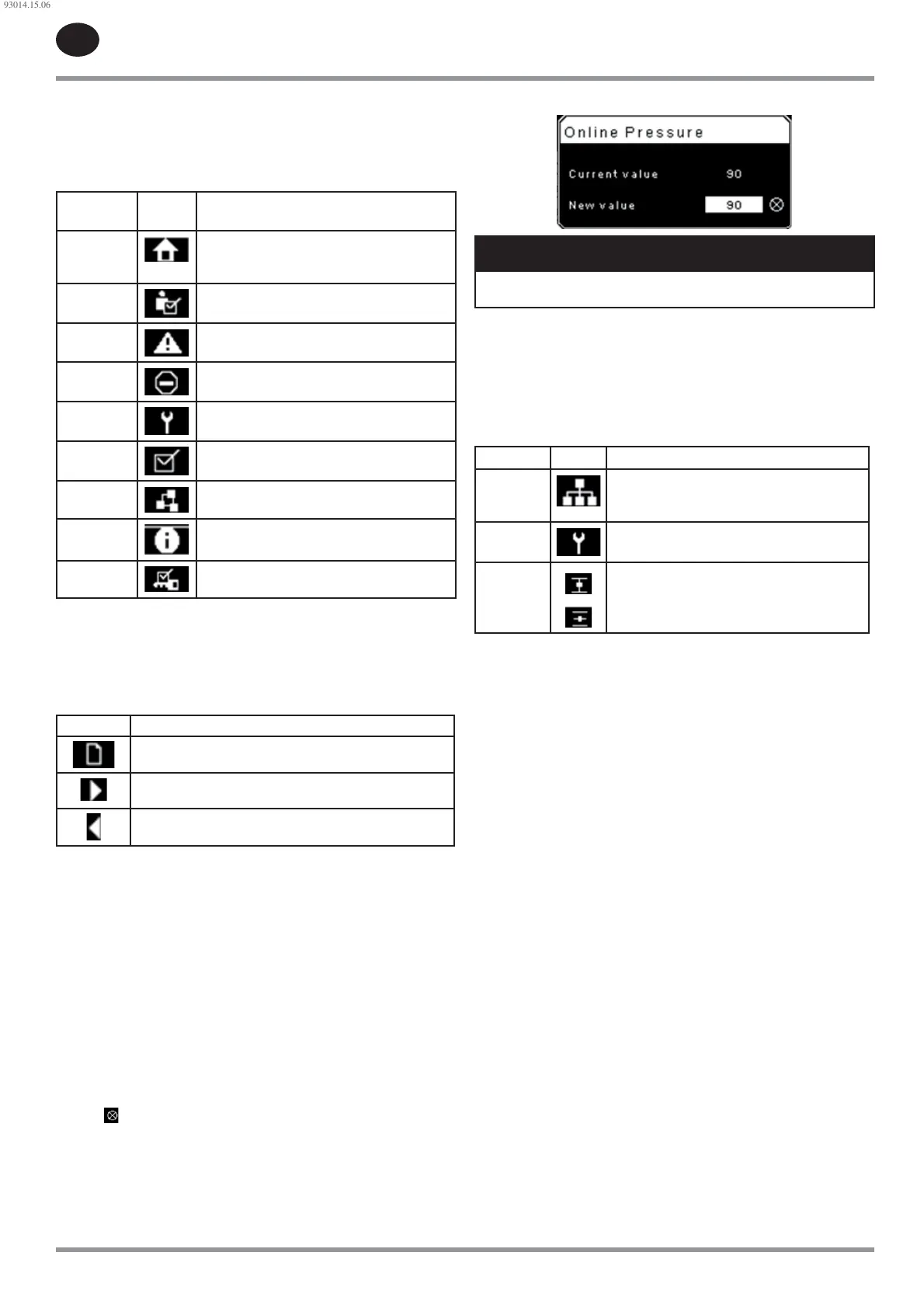
Folder navigation and icons
To move among the tabbed folders shown on the LCD display, press the
RIGHT and LEFT keys. The navigation rolls over from the last to the rst folder
and vice-versa.
Table 29 : Folder Bar Icons
Folder
Name
Icon Description
Home
System performance and status main
information. The rst page of this folder is the
default page when the controller rst powers up.
Operator
Settings
System options and con guration settings.
Events
System events log.
Trip History Details on the most recent trips.
Maintenance Status and noti cation setup for compressor
maintenance items.
General
Settings
General settings such as Language, Time, and
Units of Measure.
Integral
Sequencing
Integral Sequencing communication status and
con guration.
Status
Measurements or status from/of all analog and
digital I/O.
Factory
Settings
Compressor tuning parameters. Also displays
hardware and software versions.
Page navigation
Once the desired folder is selected, press the DOWN key to move to the page
selection area and then use the RIGHT and LEFT keys to select the desired
page. Use the UP key to get back to the folder tabs.
Table 30 : Title Bar Page Icons
Icon Description
Start of the page selection area.
Indicates that there are more pages available by navigating
right.
Indicates that there are more pages available by navigating
left.
Accessing parameters
After the desired page is selected, the page’s parameters can be selected by
using the DOWN key. The cursor will move to the next parameter each time
the DOWN key is pressed. Use the UP key to go back to the previous one.
The cursor rolls over, so once the last parameter is selected, pressing the
DOWN key will navigate the cursor to the Folder Bar. If the rst parameter is
selected, pressing the UP key will move the cursor to the page selection area.
Once selected, access parameters by pressing the ENTER key. Make changes
using the NAVIGATION keys and then enter the setting by pressing the ENTER
key again. After a parameter is accessed, pressing the ENTER key will enter
the current setting into the control program and navigate the cursor back to
the selected parameter on the page.
When the cursor is on a parameter that has an enabled/disabled box,
pressing the ENTER key will cause the setting to toggle.
This icon
appears on numeric entry windows (see Figure 69). Placing the
cursor on it and then pressing the ENTER key will cancel the entry and any
changes that were made.
Figure 69 : Numeric Entry Window
NOTICE
Not all pages have adjustable parameters. Some just have read-only
information.
Dashboard icons
The dashboard is intended to be a quick at-a-glance view of system status.
The following table lists standard dashboard icons and their de nition.
Note that the color of these icons changes based on the state set by the
application while running.
Table 31 : Dashboard Icons
Name Icon Description
Remote
Control
Remote control is enabled. This can be Remote
Start/Stop, COM Control, Integral Sequencing or
Web Control.
Service
Required
A service reminder is nearing or has expired
(i.e.: an air or oil lter needs to be changed).
Unloaded
or
Loaded
Compressor is in the unloaded state.
Compressor is in the loaded state.
Dashboard Status Messages
The dashboard also displays the current operating state of the compressor.
The following states can be encountered during machine operation:
Ready to Start – The compressor currently has no trip or start inhibit
conditions present. The machine can be started by pressing the start
button at any time.
Starting – A start command has been given to the compressor and the
start sequence is being performed. The time period for this state can vary
depending on the starter type of the machine.
Load Delay – The compressor is waiting for a small period of time after
starting before allowing the machine to load. This ensures the machine is
at operating conditions before loading.
Running Loaded – The compressor is operating and producing air. The
inlet valve is open and the blow-o valve is closed.
Running Unloaded – The compressor is operating, but not producing air.
The inlet valve is closed and the blow-o valve is open.
Reload Delay – This is a brief period of time after the compressor has
unloaded before it is allowed to load again. This gives the inlet and bypass
valves time to reach their proper positions.
Auto-Restart – The compressor has stopped due to pressure rising above
the o ine or auto-stop setpoints and auto-restart being enabled. The
compressor will automatically restart when pressure falls to the online or
target pressure setpoint.
Stopping – The compressor has received a stop command and the stop
sequence is being performed.
Blowdown – The compressor must wait for a brief period of time after
stopping its motor before it is allowed to start again. The compressor will
restart at the end of the blowdown period if a start command is recieved
during blowdown.
Not Ready – The compressor has detected a condition that will not allow
the compressor to start. The condition must be cleared before a start is
allowed, but does not need to be acknowledged.
Tripped – The compressor has detected an abnormal operational
condition that has stopped the machine. A trip must be acknowledged by
hitting the reset button before the compressor can start.
Processor Init – The controller is being initialized.
•
•
•
•
•
•
•
•
•
•
•
•
93014.15.06
 Loading...