Transmission
9803/3280 Issue 1
Powershift Gearbox
Component Identification
A Torque converter
B Forward/input clutch assembly
C Reverse clutch assembly
D Mainshaft assembly
E Layshaft assembly
F 2/4 wheel drive clutch assembly
G Torque converter relief valve
H Oil pressure maintenance valve
J Transmission oil pump
K 6 speed assembly (if fitted)
L 4WD output yoke
M Hose connection - to oil cooler
N Hose connection - from oil cooler
P Oil strainer
Q Oil filter
R Driveshaft (drives machine main hydraulic
pump)
1 Speed sensor
2 Gear drive to reverse unit clutch assembly
3 Transmission oil pressure switch
4 Steering column mounted gear selection switch
5 Solenoid control valves
6 Gearbox oil cooler
Principle of Operation
The JCB Powershift is an electro-hydraulic
transmission unit. Gear shifting and direction
selection are controlled using multi-disc clutch
packs.
Electrically operated solenoid valves 5 divert
pressurised oil (provided by pump J) to the
selected clutch packs.
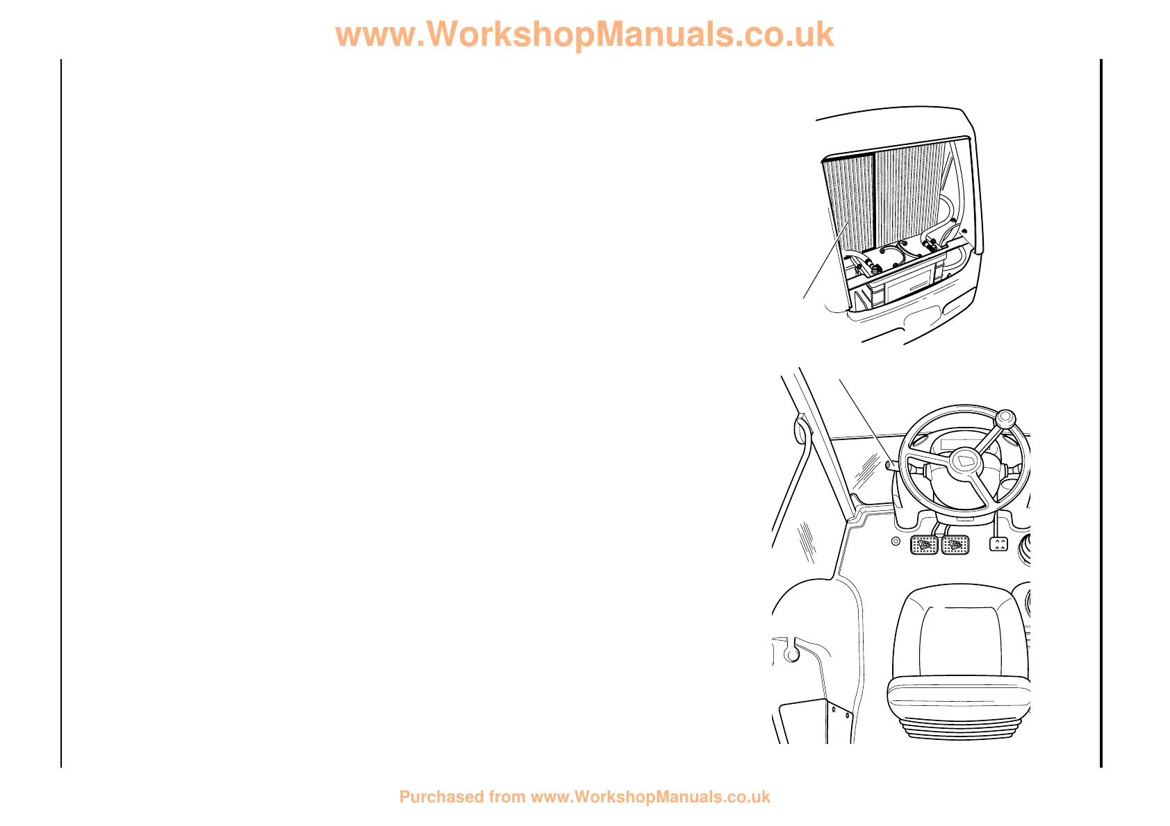
A combined lever/swivel switch 4 on the steering
column actuates both gear ratio and direction
solenoids.
The Powershift unit consists of a torque converter
A, forward clutch assembly B, reverse clutch
assembly C, layshaft assembly E, mainshaft
assembly D, 2/4 wheel drive clutch assembly F.
6 speed gearboxes incorporate a ‘6 speed’ shaft
and clutch assembly K.
The forward clutch assembly B is driven by the
torque converter A. The reverse clutch assembly C
is permanently driven via constant meshing of spur
gears 2. On 6 speed gearboxes the 6 speed
assembly is also driven via meshing gears 2.
Driveshaft R is permanently driven by the engine
and runs through the hollow forward/reverse unit
shaft to the back of the gearbox. The shaft (R)
drives the gearbox mounted machine main
hydraulic pump.
Strainer P and filter Q are used to prevent potential
system contamination by filtering dirt particles.
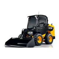
Gearbox oil is cooled by an air blast cooler 6. The
cooler is part of the front mounted machine ‘cooling
pack’.
17 - 2 17 - 2
Basic Operation
Section F Section F
 Loading...