Home
JUKI
Industrial Equipment
FX-1
JUKI FX-1 User Manual
5
of 1
of 1 rating
212 pages
Give review
Manual
Specs
To Next Page
To Next Page
To Previous Page
To Previous Page
Loading...
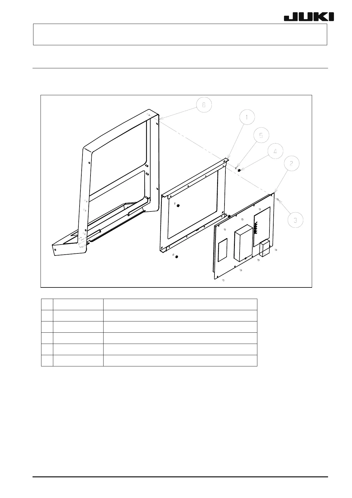
FX-1/FX-1R Maintenance
Manual
12-3.
Replacing the LCD Monitor
12-3-1.
Replacing the LCD Monitor
12-3
c
L180E221000 LCD
FRAME
d
L910E121000 LCD
e
SL4030691SC
SEMS cap bolt, M3
×
6
f
NM6040001SC
Hexagon nut, M4
g
WS0410002KN
Spring washer, M4
h
L180E121000 OPERATION
BOX
Rev. 2.00
118
120
Table of Contents
Default Chapter
9
Table of Contents
9
X-Y Unit
15
Replacing the Timing Belt and Adjusting the Belt Tension
15
Timing Belt YM
15
YB-Belt
16
Adjustment Procedure
17
Measurement Positions and Specification Values
17
Adjusting Method
18
Replacing the Pulleys
19
Replacing the Pulley YA
19
Replacing the Pulley YM
19
Replacing the Pulley YB
19
Replacing the Servomotors
19
Replacing the Magnescale (for FX-1R, See Section 1-8.)
20
X-Axis Magnescale Affixing Position (for FX-1R, See Section 1-8-1.)
20
Y-Axis Magnescale Affixing Position (for FX-1R, See Section 1-8-2.)
21
Gap of Magnescale (for FX-1R, See Section 1-8-4.)
21
Replacing the Limit Sensor and the X-Axis Home Position Sensor
22
Replacing the XL-, XR-, and XC-Limit Sensors
22
Replacing the YB- +/−Limit Sensors and YB-Near Sensor
22
Replacing the Home Position Sensor
23
Y-Axis
23
Replacing the Plastic Rail
24
Replacing the X-Axis Plastic Rail
24
Replacing the Y-Axis Plastic Rail
25
Replacing the Magnescale (FX-1R)
26
X-Axis Magnescale Affixing Position (FX-1R)
26
YB-Axis Magnescale Affixing Position (FX-1R)
27
YA-Axis Magnescale Affixing Position (FX-1R)
27
Gap of Magnescale (FX-1R)
28
Head Unit
29
Replacing and Adjusting the Head
29
MNLA Head
29
Replacing the Motor
32
Z-Motor (MNLA Head)
32
Θ-Motor (MNLA Head)
34
Replacing the Z-Sensor
35
MNLA Head
35
Replacing the Laser Sensor
36
Replacing the MNLA
36
Replacing the Head up Spring
37
MNLA Head
37
Replacing the Belts
38
MNLA Head
38
Replacing the Spline Housing
39
Replacing the Nozzle Outer Shaft Assembly
40
List of Readjustment Items after Replacement
41
Parts Around the Head
42
Replacing the Ejector Unit
42
Replacing the Bad Mark Sensor
43
Sensor Assembly
43
Adjusting the Sensor Height
43
Amplifier
44
Assembling the Fiber Unit to the Amplifier
44
Setting the Switches on the Bad Mark Sensor Assembly
44
Running the Bad Mark Sensor Cables
45
Replacing the HMS
46
Replacing the HMS Head
46
Replacing the HMS Amplifier
46
Sticking the Label
47
Mounting the Board
47
Running the HMS Cables
48
Adjusting the HMS Height
50
Replacing the Head Board
51
Replacing the Head Main Board
51
Replacing the Sensor Relay Board Assembly
52
Occ Assembly
53
Replacing the OCC Assembly
53
Replacing the CCD Camera and Lens
54
Replacing the OCC Coaxial/Angle Light Board Assemblies
55
Replacing the Lens Filter and Light Filter
56
Adjusting the Focus
57
Adjusting the OCC Light Quantity
58
List of Readjustment Items after Replacement
58
Board Transport Unit
59
Replacing the Transport Belt
59
Replacing the Transport Pulley
60
Conveyor Pulley A: E21117150A0
60
Conveyor Pulley B: E20897210A0
60
Replacing the in and out Motors
61
Replacing the CENT Motor and AWCC Motor
63
Adjusting the Width Adjust Link Belt (CENTER)
65
Adjusting the Width Adjust Link Belt (IN/OUT)
66
Replacing the in and out Sensors
67
Replacing the WAIT Sensor and C out 2 Sensor
68
Replacing the Fiber
68
Replacing the Amplifier Unit
69
Replacing the STOP and C out Sensors
70
Replacing the Stopper Cylinder
72
Replacing the STBL Home Position Sensor
73
Replacing the T-PIN Sensor
74
Adjusting the Position in the Y-Direction (Outer Shape Reference)
75
Replacing the Check Cylinder (Outer Shape Reference)
75
Adjusting the Check Cylinder Speed
76
Replacing the Centering Pin
77
Replacing the STBL Motor
78
Adjusting the Gap between Torque Supporter and STBL Motor
78
Adjusting the Tension of the STBL Driving Timing Belt
79
Placing the Support Table Surface Horizontally
79
Replacing the STBL Encoder
80
Layout of Solenoid Valves
81
Replacing the Support Pin Detection Sensor
82
Replacing the YA-Motor
83
Adjusting the Z-Phase of the YA-Ball Screw
84
Cal Block
85
Replacing the CAL Block Board Assembly
85
Replacing the Ejector
86
Replacing the Vacuum Calibration Sensor
87
Atc
88
Replacing the Air Cylinder
88
Replacing the ATC OPEN and CLOSE Sensors
91
Adjusting the Speed Controller
91
Feeder Bank and Replacement Table (Optional)
92
Overall Drawing
92
Replacing the Drive Cylinder
93
Adjusting the Speed Controller of the Drive Cylinder
95
Replacing the Feeder Bank Board and Feeder I/F Board
96
Replacing the Bank-Up Cylinder
97
Adjusting the Speed Controller of the Bank-Up Cylinder (Optional Replacement Table)
98
Replacing the Bank-Up Detection Sensor (Optional Replacement Table)
99
Replacing the Selector Switch (Optional Replacement Table)
100
Replacing the Roller Lever (Optional Replacement Table)
101
Pneumatic Units
102
Replacing the Main Pressure Detection Cable Assembly
102
Replacing the Filter Element
103
Switches
105
Replacing the Push-Button Switch
105
Replacing the EMERGENCY STOP Switch
107
Replacing the Cover Open Switch
109
Switch Main Unit
109
Operation Key
110
Replacing and Adjusting the Feeder Float Sensor
111
Other Units
117
Replacing the FDD (Floppy Disk Drive)
117
Replacing the CD-ROM Drive
118
Replacing the LCD Monitor
119
Setting up the Touch Panel (Optional)
120
Replacing the LCD Back Light
121
Adjusting the LCD
122
Replacing the SSD
124
Required Components
124
Replacing the HDD
125
Setting up the BIOS
126
Setting up the Network (this Setup Is Performed When Communicating with the HLC)
129
Installing the FX-1-Series System Programs and Flexline DB
147
Changing the Windowsnt Product ID
152
Restoring the C Drive to the Initial Status
154
Electrical Components
155
Layout of Electrical Components
155
Part Names
155
Layout of Top of Base Frame
156
Part Names
156
Power Supply Unit
157
Structure of Power Supply Unit
157
Control Unit
160
Structure of Control Unit
160
CPU Board (40003280)
162
Position Board (12-Axis: L901E621000, 24-Axis: L901E721000)
163
Bus Bridge Board (40003313)
164
MCM (Multi Nozzle Control Module) Board (E9609729000)
165
SAFETY Board (40007368)
166
BASE FEEDER Board Assembly (40007370)
168
I/O Control Board (40001943)
170
Light Ctrl Board (40001918)
172
IP-X3 Board (40001920)
173
POS-CNN Board (40007372)
175
SCALE-I/F Board (40013604)
175
X-Y Unit
176
Structure of X-Y Unit
176
XY-Axis Driver Indication Display
177
Scale I/F Unit
177
Magnescale Detector (Used in FX-1; Not Used in FX-1R)
178
Z-Θ Unit
179
Structure of Z-Θ Unit
179
LED Indications
180
Transport Unit
181
Structure of Transport Unit
181
Adjusting the CONVEYOR Board
182
Adjusting the Stepping Driver
183
Thermal Sensor Board
185
Head Unit
186
Boards Used on the Head Unit
186
Adjusting the Boards of the Head Unit
187
Covers
189
Structure of Operation Unit
189
Jumper Settings of OPERATION PCB ASM (40012048)
189
Mounting the Switches on the OPERATION SW PCB ASM
190
Jumper Switch Settings of Operation Sw PCB ASM (40012050)
194
Ups (40003292)
195
Checking the UPS Battery (E9659729A000) Voltage
195
Replacing the UPS Battery
196
Hod
199
Adjusting the Light Quantity of the HOD LCD
199
Replacing the HOD LCD
200
BANK/FPI-F(R) Board Assembly
202
Auto Board Width Adjustment
203
Assembling the AWC Bracket
203
Assembling to the Machine Main Unit
204
Mounting the AWC Bracket Assembly
204
Mounting the Origin Switch Dog
205
Running the Cables and Setting up the Driver
206
Feeder Position Indicator (Fpi)
208
Detaching the FPI from the Machine Main Unit
208
Structure of Components Inside FPI
209
Jig Lists
210
5
Based on 1 rating
Ask a question
Give review
Questions and Answers:
Need help?
Do you have a question about the JUKI FX-1 and is the answer not in the manual?
Ask a question
JUKI FX-1 Specifications
General
Brand
JUKI
Model
FX-1
Category
Industrial Equipment
Language
English
Related product manuals
JUKI FX-3R
251 pages
JUKI FX-1R
212 pages
JUKI TR6SNR
126 pages
JUKI KE-760
59 pages
JUKI JX-100
41 pages
JUKI KE-2070
43 pages
JUKI KE-2010
52 pages
JUKI KE-2080
43 pages
JUKI KE-2050
290 pages
JUKI KE-3010
414 pages
JUKI KE-2060R
290 pages
JUKI KE-2000 Series
52 pages
 Loading...


