FX-1/FX-1R Maintenance Manual
5-16. Replacing the Centering Pin
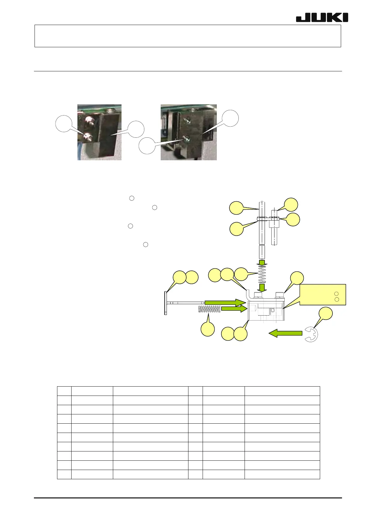
(1) Loosen the screws d, e and g of the guide block A c and B f to detach the centering pin
together with the guide blocks.
5-19
d
f
e
c
Figure 5-16-1 Figure 5-16-2
(2) At this time, also detach the T-PIN sensor (together with its bracket) from the reference side.
Removing the E ring
13
allows
you to pull the centering pin
18
from the damper block.
Removing the E rings
17
(two in
total, top and bottom) allows you
to remove the centering pin
18
.
When installing a new centering
pin, reassemble the components
in the reverse order. The E-rings
must also be replaced with new
ones.
After the components have been
reassembled, adjust the sensor
position in the same manner as
described in 5-12, Replacing the
T-PIN Sensor.
⑪
i
h
⑯
j
k
B部
右側=⑦+⑩+⑫
左側=⑧+⑪+⑫
Section B
Right side = ⑦+⑩+
12
Left side = ⑧+⑪+
12
⑫
⑬
g
l
⑰
⑮
⑭
⑱
Fi
ure 5-16-3
Table 5-16-1
Part No. Part name Part No. Part name
1 L162E621000 GUIDE BLOCK LL 10 L179E621000 DAMPER BLOCK L
2 L162E721000 GUIDE BLOCK RL 11 L179E721000 DAMPER BLOCK R
3 SM6031402TN BROCK FIX BOLT 12 SL6030892TN DAMPER PLATE FIX BOLT
4 SL6031492TN BROCK FIX BOLT 13 RE0300000K0 E RING
5 40000891 STOPPER SLIDE LEVER L 14 40000896 DAMPER LOCK PIN
6 40000897 STOPPER SLIDE LEVER R 15 40000978 DAMPER LOCK LINK
7 40015791 DAMPER PLATE L 16 40000950 DANPER SPRING
8 40015792 DAMPER PLATE R 17 RE0300000K0 E RING
9 40015793 LOCK SPRING 18 40001081
CENTERING PIN φ4
Rev. 2.00
 Loading...


