FX-1/FX-1R Maintenance Manual
13-9-4. Jumper switch settings of operation sw PCB ASM (40012050)
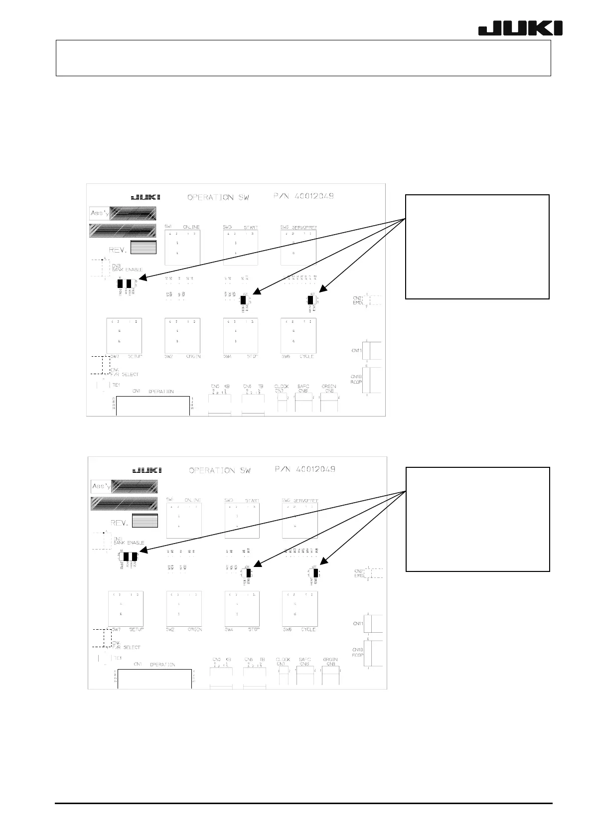
Check the jumper switch settings of the OPERATION SW PCB ASM while referring to the following
figures.
(1) Front
Check that the receptacle is
mounted between 1 and 2
and between 5 and 6 o
W1, between 1 and 2 o
W26, and between 1 and 2
of W27, and that no
receptacles are mounted
on other jumper switches.
(2) Rear
Check that the receptacle is
mounted between 3 and 4
and between 7 and 8 o
W1, between 3 and 4 o
W26, and between 3 and 4
of W27, and that no
receptacles are mounted
on other
umper switches.
13-40
Rev. 2.00