FX-1/FX-1R Maintenance Manual
3-4. Replacing the Head Board
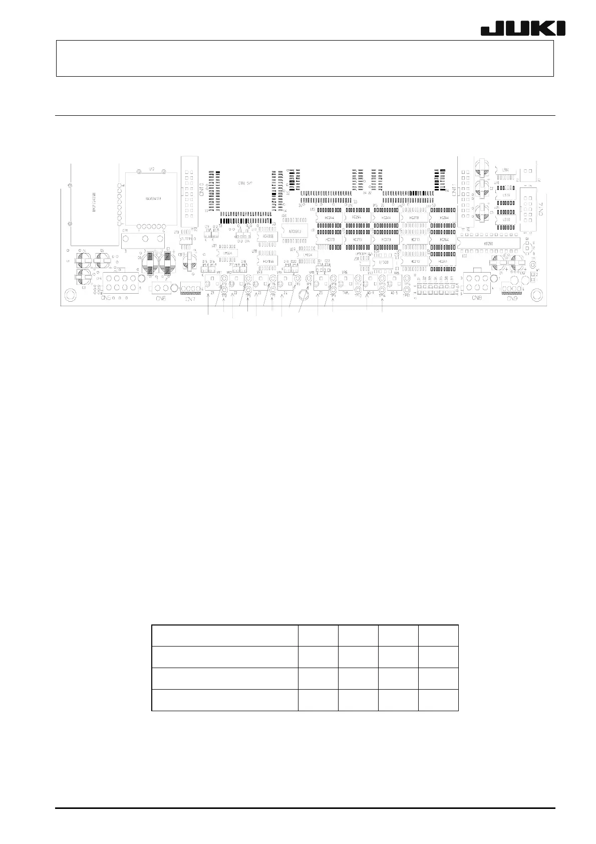
3-4-1. Replacing the Head Main Board
TP2
TP3
TP4
TP5
TP6
TP7
TP8
TP9
TP2
TP3
VR7
TP14
VR2
VR1
VR3 VR4
VR5
Figure 3-4-1 Head Main Board
After the head main board has been replaced, adjust the vacuum level. (At this time, use TP1 for the
GND terminal.)
<Procedure>
1. Adjusting the VR7 (the reference voltage of the A/D converter)
c Monitoring the voltage of TP14 with a voltmeter, rotate the VR7 to adjust the voltage to 1.25 ±
0.01 V.
2. Adjusting the VR1 through VR4 (the vacuum input voltages)
c Attach the 503 nozzle to the axis to be adjusted and turn the vacuum on.
d Measure the voltage Vvac at the external input check terminal with a voltmeter and record the
result.
e Monitoring the voltage of the A/D input check terminal with a voltmeter, rotate the vacuum
input voltage controller to adjust the voltage to (Vvac/2) ± 0.01 V.
The relationship among the heads, check terminals and controller are as follows:
Head L1/R1 L2/R2 L3/R3 L4/R4
Vacuum input voltage controller VR1 VR2 VR3 VR4
External input check terminal TP3 TP5 TP7 TP9
AD input check terminal TP2 TP4 TP6 TP8
Notes 1. Before adjusting the controller, check that the DC power output voltage has been
adjusted.
Notes 2. Check that the sensors related to the controller adjustment are connected
properly.
3-10
Rev. 2.00
 Loading...


