FX-1/FX-1R Maintenance Manual
13-4. Control Unit
13-4-1. Structure of Control Unit
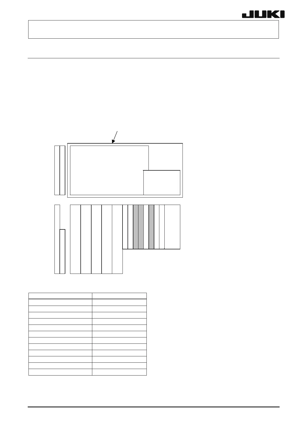
Figure 13-4-1-1 shows the board layout drawing of the control unit; Check that the boards are
mounted correctly while referring to these figures.
13-4-1-1. Board Layout
SAFETY
BASE−FEEDER
ランク 注1
ランク 注1
LIGHT−CTRL
MCMR(R)
IP−X3
I/O−CTRL
MCMR(L)
ション
ー
12軸
ション
ー
24軸
ランク 注1
ス
リッ
ー
CPUボード
SCALE−I/F
POS−CNN
CPU board
Position board, 12-axis
Blank
Note 1
Position board, 24-axis
Blank
Note 1
Blank
Note 1
Bus brid
e board
VMEバックボード
CPCIバックボード
POS−CNN
SCALE−I/F
CPCI back board
VME back board
ラック
Rack
正面視
Front view
上面視
Top view
Note 1. Mount the blank panel (E1649729000) to the blank slots.
Board name Part No.
CPU board 40003280
Position board, 12-axis L901E621000
Position board, 24-axis L901E721000
Bus bridge board 40003313
MCM board E9609729000
IP-X3 board 40001920
I/O-CTRL board 40001943
BASE FEEDER board 40007370
LIGHT CTRL board 40001918
SAFETY board 40007368
SCALE I/F board L901E921000
POS CNN board 40007372
Figure 13-4-1-1 Board Layout Drawing
13-6
Rev. 2.00
 Loading...


