FX-1/FX-1R Maintenance Manual
5-17
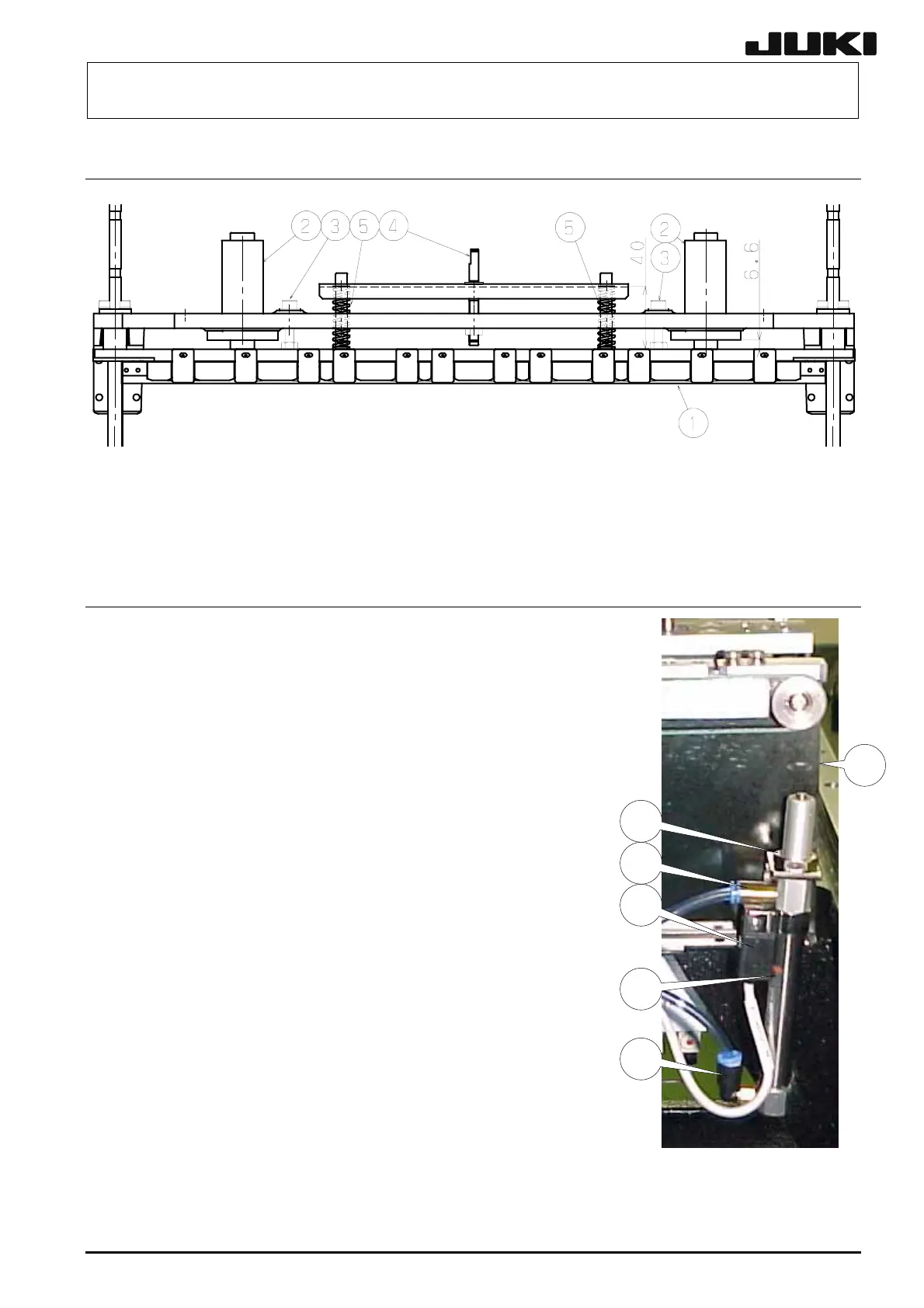
5-13. Adjusting the Position in the Y-direction (Outer Shape Reference)
13-1 Figure 5-
(1) Put e block a the bolts e to make the adjustment so that the gap between
the rail base R c a omes 6.6 mm.
Turn the rail guide f spring length g to 40 mm.
5-14. Replacing the Check Cylinder (Outer Shape Re
the gaug nd tighten
nd bushing d bec
(2) to adjust the
ference)
c
d
e
f
g
h
(1) Loosen the mounting nut d to detach the cylinder c.
(2) Remove the elbow union e, half union f, and cylinder sensor g
from the detached cylinder c.
(3) Reassemble the components
in the order of steps (3) to
(1).
When reassembling the
components, carefully check the following items.
(1) Reassemble the components so that the top end of the
cylinder rod is aligned with the end face of the rail plate h
when the cylinder is ON.
(2) To adjust the sensor position, follow the steps below.
• Loosen the sensor position adjustment screw.
• Adjust the transport width of the IN/OUT buffer to
the 0.4mm-PWB.
• Set the adjustment PWB so that it is projected from the
IN/buffer.
• Select [Manual Control] and [Check Cylinder] in that order
to activate the cylinder and put the PWB between check
brackets.
• In the above status, lower the sensor position so that the sensor
is turned ON. (Position A)
• Set the sensor at the medium position between the position A
and the upper limit position of the sensor, and then fix it.
• In the status that the adjustment PWB is removed, operate the
cylinder repeatedly to check that the sensor is turned ON steadily.
Figure 5-14-1
STOP CYLINDER: E2254802000
CHECK SENSOR (F): L828E6210A0
CHECK SENSOR (R): L828E4210A0
Rev. 2.00