FX-1/FX-1R Maintenance Manual
13-4-3 Position board (12-axis: L901E621000, 24-axis: L901E721000)
[Functions]
This position board is a CPCI bus applicable board that controls the servomotors and stepping
motors through SSCNET II, Mitsubishi Electric’s control communication network.
Up to 12/24-axis motors are controlled.
c Instructions are received from the software on the CPU board to control the
XYZθ-servomotors and transport pulse motors.
d The origin sensor and limit sensor of each axis are detected.
e The servo driver alarm and magnescale alarm are detected.
f The EMERGENCY STOP switch is detected to stop the XY-axis, Zθ-axis, and transport axis.
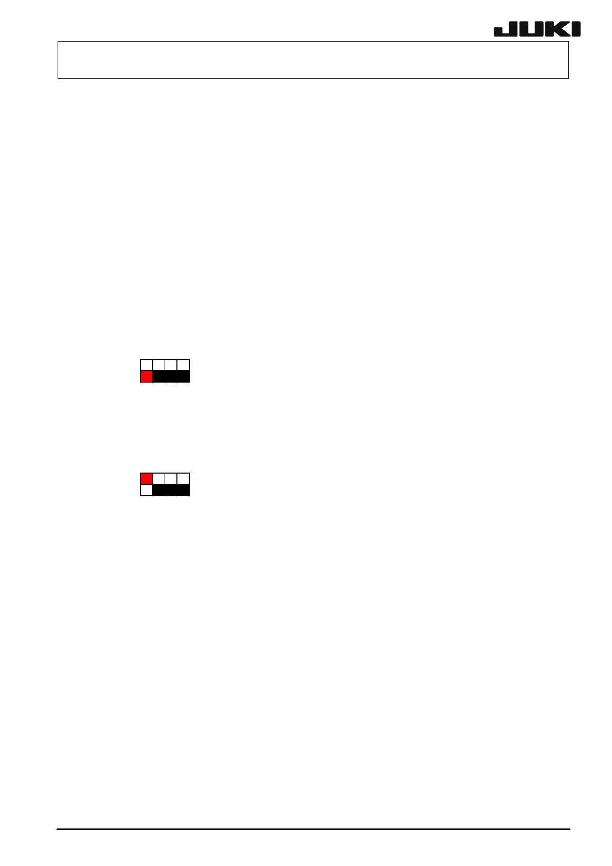
[Dip switch settings]
CH, 2CH: Green LED is lit during normal operation.
24-axis 1 to 4CH: Green LED is lit during normal operation.
ent items lac
ジション
ード12軸(2ch)
1234
ON
SW1
ジション
ード24軸(4ch)
1234
ON
SW1
Position board, 24-axis (4 ch)
Position board, 12-axis (2 ch)
[Meaning of LED]
12-axis 1
[Adjustm after rep ement]
There are no particular adjustment items.
13-9
Rev. 2.00
 Loading...


