FX-1/FX-1R Maintenance Manual
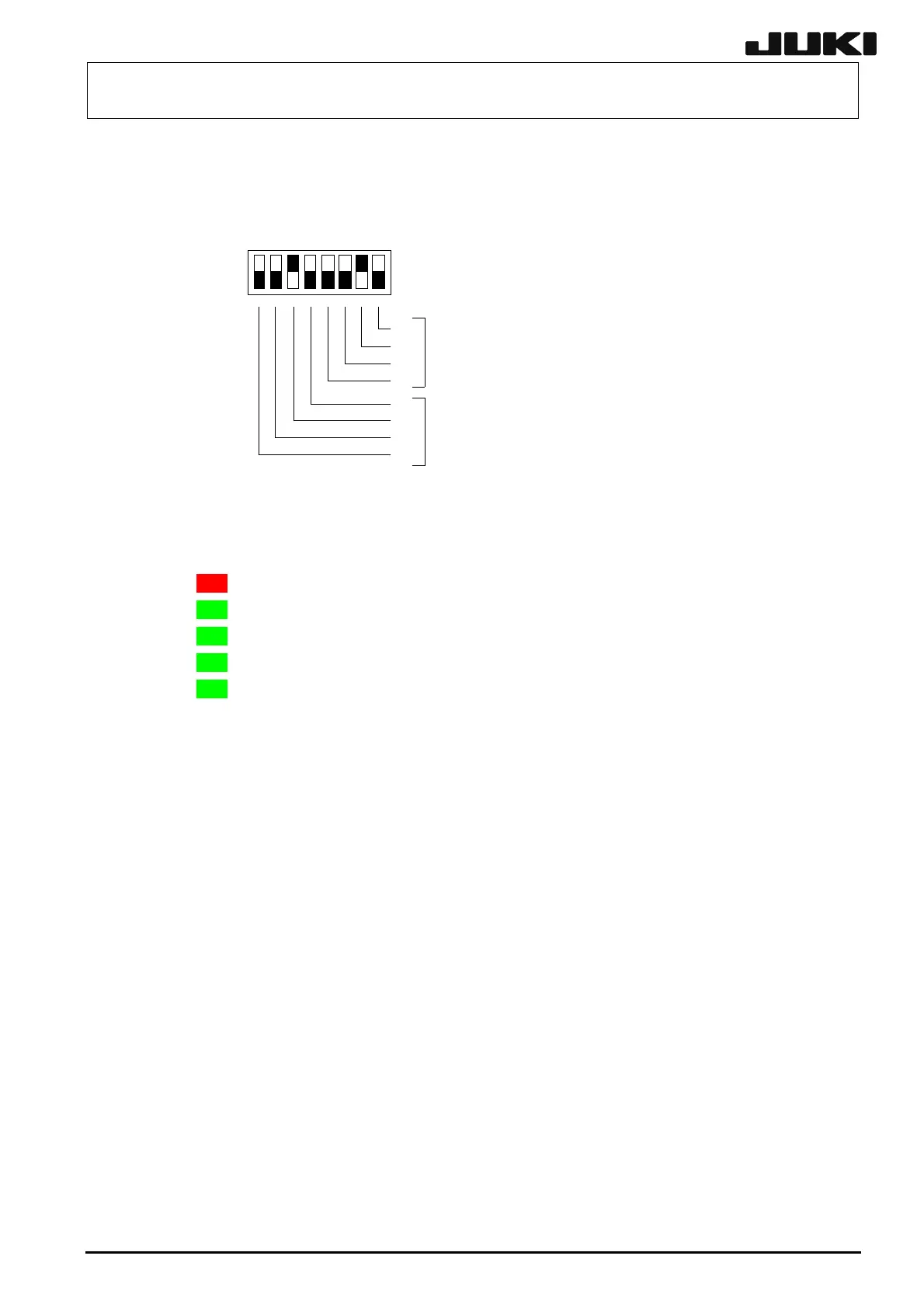
Use the switch 1 to set the function Rev. and pattern Rev. of the board. The following figure
shows the assignment and weight of each bit. The setting shown in this figure means that the
function Rev. is set at “02” and the pattern Rev. is set at “02”.
ON
OFF
18
機能Rev.設定
パターンRev.設定
2
0
2
2
2
1
2
3
2
0
2
2
2
1
2
3
SW1
Pattern Rev. setting
Function Rev. setting
[Meaning of LED]
5 LEDs are mounted on the SAFETY board and have the following meanings.
ALM LED1 YA軸リミット、YB軸リミット、非常停止が検出された場合に点灯
COSW に点灯
AREA−F ない
AREA−R ない
F−FLOT
LED2 カバーオープンが検出された場合
LED3 使用し
LED4 使用し
LED5 フィーダ浮きセンサが検出された場合に点灯
LED 1: Lights up if activation of the YA-limit sensor, YB-limit sensor, or emergency stop switch is detected.
LED 2: Lights up if the cover open is detected.
LED 3: Not used.
LED 4: Not used.
LED 5: Lights up if the activation of the feeder float sensor is detected.
[Adjustment items after replacement]
After the replacement has been completed, it may be required to back up the MS parameters.
From the menu bar, select [File] and [Control Data Management] to back up the MS parameters.
13-13
Rev. 2.00
 Loading...


