FX-1/FX-1R Maintenance Manual
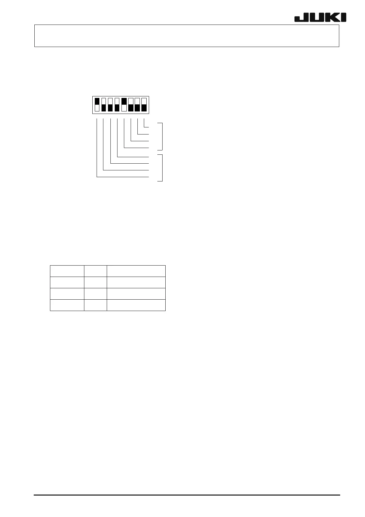
Use the switch 4 to set the function Rev. and pattern Rev. of the board. The following figure
shows the assignment and weight of each bit. The setting shown in this figure means that the
function Rev. is set at “01” and the pattern Rev. is set at “01”.
ON
OFF
18
2
3
2
2
2
2
1
0
2
3
2
2
2
2
1
0
SW2
on
SW4
off
パターンRev.設定
機能Rev.設定
Pattern Rev. setting
Function Rev. setting
[Switches on front panel]
RESET switch: Resets this board.
ABORT switch: Issues NMI to the host CPU.
Normally, do not operate these two switches.
[Meaning of LED]
LED No. Color State of the indicator
LED 1 Red FAIL
LED 2 Red HALT
LED 3 Green Normal
[Adjustment items after replacement]
If the version of the ROM mounted on the new board is different from that on the old board or if no
ROM is mounted on the new board, remove the ROM from the old board and mount it on the new
board.
After that, follow the steps below to update the FLASH memory.
c Select [Options] and [Change User Group], and then select [Serviceman].
d Select [Maintenance] and [MS Parameter Setup].
e Select [Others], [Version-up], and [I/O].
13-17
Rev. 2.00
 Loading...


