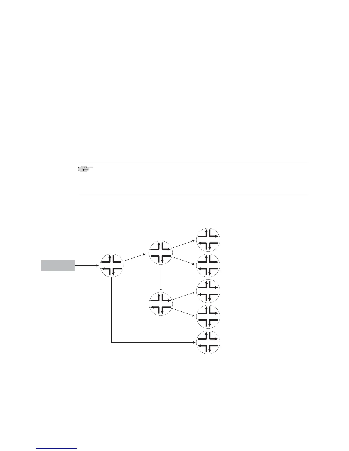
Figure 61 on page 264 shows a point-to-multipoint LSP with multiple egress LSRs.
The multicast source sends a packet to the ingress router, LSR 1, which in turn sends
the packet on the point-to-multipoint LSP to the branch router, LSR 2. The branch
router, LSR 2, is connected to another branch router, LSR 3. Here, LSR 3 is not directly
connected to the ingress router, LSR 1, but only to the branch router, LSR 2. These
branch routers, in turn, replicate the packet and forward it to E Series routers, LSRs
4 through 7, configured as egress LSRs.
The configuration shown in Figure 61 on page 264 is an example of an LSP that
contains segments that run from ingress LSR to one or more branch and egress LSRs.
For example, sub-LSPs exist between LSR 1 and LSR 2, and between LSR 2 and LSR
4. The sub-LSP between LSR 2 and LSR 4 is an egress sub-LSP that transmits the
replicated packet from branch router, LSR 2, to egress E Series router, LSR 4. Egress
LSRs can also be directly connected to the ingress LSR. In this figure, the connection
between LSR 8 and LSR 1 is an example of this type.
NOTE: You cannot use E Series routers as core or ingress LSRs. You need to use
Juniper Networks routers running JUNOS software to function as core or ingress LSRs
in the point-to-multipoint LSP.
Figure 61: Simple MPLS Domain
Branch routers
Egress routers
LSR 2
LSR 3
LSR 7
LSR 6
LSR 5
LSR 4
g016488
Sub-LSP
Ingress router
LSR 1
Multicast source
LSR 8
Use the show mpls rsvp tunnels p2mp role tail command to view the status and
configuration information for point-to-multipoint egress tunnels.
Related Topics Monitoring Status and Configuration for MPLS Tunnels■
■ show mpls tunnels
264 ■ Point-to-Multipoint LSPs Overview
JUNOSe 11.1.x BGP and MPLS Configuration Guide
 Loading...