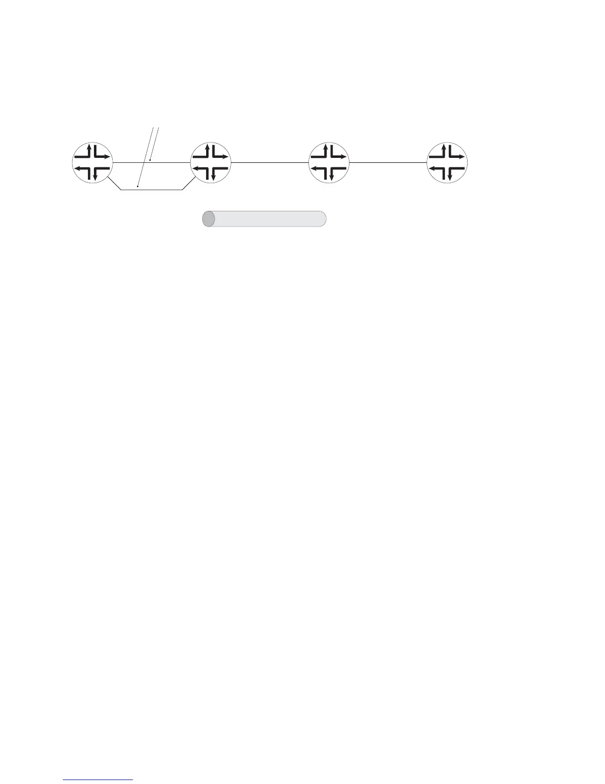
Figure 122: MPLS L2VPN Tunnel over VLAN over LAG Configuration Example
PE1CE1 CE2PE2
g016507
7.7.7.7/24 11.11.11.11/32 22.22.22.22/32 7.7.7.8/24
2/1/0
2/1/3
2/1/1
2/1/2
2/1/4
2.0.0.1/24
vlan id 20
2/1/5
2.0.0.2/24
2/1/6 2/1/7
MPLS LDP signaling
Martini tunnel
mpls-relay with vcid = 1
lag 1 lag 2
svlan 1 1 svlan 1 1
CE-Side MPLS L2VPN over LAG
Configuration on CE1 (Local CE Router)
Use the following commands on the local CE router (CE1) to configure the MPLS
L2VPN tunnel shown in Figure 122 on page 548.
! Configure a virtual router CE1.
host1(config)#virtual-router ce1
!
! Specify the interface for the LAG bundle lag 1 that groups all Ethernet physical
! interfaces between CE1 and PE1.
host1:ce1(config)#interface lag 1
!
! Add the Gigabit Ethernet physical interfaces to the LAG bundle named lag 1.
host1:ce1(config-if)#member-interface gigabitEthernet 2/1/0
host1:ce1(config-if)#member-interface gigabitEthernet 2/1/3
!
! Specify VLAN as the encapsulation method for the Ethernet interface.
host1:ce1(config-if)#encapsulation vlan
!
! Specify another subinterface in the LAG bundle lag 1.1.
host1:ce1(config-if)#interface lag 1.1
!
! Assign an S-VLAN ID and a VLAN ID for the subinterface, and assign an IP
! address and mask to the interface.
host1:ce1(config-subif)#svlan id 1 1
host1:ce1(config-subif)#ip address 7.7.7.7 255.255.255.0
Configuration on PE1 (Local PE Router)
Use the following commands on the local PE router (PE1) to configure the MPLS
L2VPN tunnel shown inFigure 122 on page 548.
! Configure a virtual router PE1.
host1(config)#virtual-router pe1
!
! Enable MPLS on a virtual router in Global Configuration mode.
host1:pe1(config)#mpls .
!
! Configure the LSR to create topology-driven LSPs. Enabling LDP automatically
! creates topology-driven LSPs.
host1:pe1(config)#mpls topology-driven-lsp
548 ■ MPLS L2VPN Tunnel over VLAN over LAG Configuration Example
JUNOSe 11.1.x BGP and MPLS Configuration Guide
 Loading...