Each bypass tunnel provides 1:N local protection; that is, each bypass tunnel can
protect one or more links depending on where you have configured it. The protected
primary LSPs are stacked over the bypass tunnel to redirect their traffic around the
failure.
The bypass tunnel naturally protects all LSPs that share the bypassed link (the LSP
segment from the PLR to the downstream node) and that have requested protection.
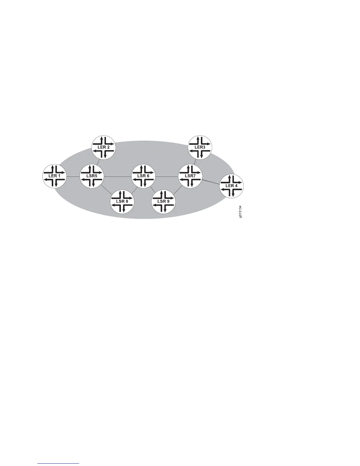
Consider the network shown in Figure 63 on page 289.
Figure 63: Bypass Tunnel
Suppose you have configured both LER 1 and LER 2 to request bypass protection,
and have configured the following two bypass tunnels:
LSR 5 –> LSR 8 –> LSR 6
LSR 6 –> LSR 9 –> LSR 7
If link LSR 5 –> LSR 6 fails, RSVP-TE redirects traffic through LSR 5 –> LSR 8 –>
LSR 6. If link LSR 6 –> LSR 7 fails, RSVP-TE redirects traffic through LSR 6 –> LSR
9 –> LSR 7. These two bypass tunnels therefore protect all LSPs routed from LER 1
or LER 2 through LSRs 5, 6, and 7. Notice in Figure 63 on page 289 that if both
protected links fail, traffic is still safely redirected through LSR 5 –> LSR 8 –> LSR
6 –> LSR 9 –> LSR 7.
If you want to protect an LSP that traverses N nodes against a failure in any link,
then you must configure N-1 bypass tunnels. As shown in Figure 63 on page 289,
each of those bypass tunnels in turn can protect multiple tunnels.
On detecting the link failure, the PLR redirects traffic arriving on all of the protected
primary tunnels to the bypass tunnel that protects the failed link. An additional label
representing the bypass tunnel is stacked on the redirected packets. This label is
popped either at the router that is the remote end of the protected link or at the
penultimate hop. The merge point therefore sees traffic with the original label
representing the primary tunnel.
When the ingress router learns by RSVP-TE signaling that local protection (a bypass
tunnel) is in use, it attempts to find a new optimal path for the tunnel, based on the
configured path options. The ingress router sets up the new tunnel before it tears
down the old tunnel with the failed link, and switches its traffic to the new tunnel.
Configuring RSVP-TE Fast Rerouting with RSVP-TE Bypass Tunnels ■ 289
Chapter 3: Configuring MPLS
 Loading...