PE devices and the configuration of the S-VLAN subinterface on CE-facing devices,
a device in the Maritni circuit can be either S-VLAN-aware or S-VLAN-unaware.
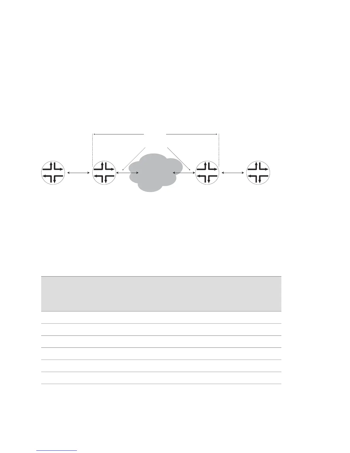
Figure 124 on page 555 shows a Martini circuit deployment in which the CE-side
devices on either side of the network send and receive Ethernet frames. The packets
reaching the CE-side devices can be S-VLAN-aware or not. The MPLS network might
also be S-VLAN-aware or not, which means that S-VLAN tags might or might not be
sent over the MPLS cloud.
Figure 124: MPLS L2VPN Tunnel over LAG Configuration Example
PE1CE1 CE2PE2
MPLS network
Ethernet traffic
g016510
Ethernet traffic
Martini tunneling
Pseudowire
The cases in which the MPLS network is S-VLAN-aware, but the CE-side device is not
S-VLAN-aware, are supported because the Ethernet pseudowire operates in tagged
mode. When the pseudowire is configured for raw mode, only two cases are
supported: whether the CE-side device is S-VLAN-aware or not aware.
Table 67 on page 555 describes the different scenarios in which the Martini circuit
shown in Figure 124 on page 555 can be deployed depending on whether the various
network segments are S-VLAN-aware or not
Table 67: Martini Circuit Scenarios Without Ethernet Raw Mode
Whether scenario is
supported, when raw
mode is not configured
on the S-VLAN
interface
Receiving CE
Device (CE2)
MPLS network
between local and
remote routers, PE1
and PE2Sending CE device (CE1)
Case
number
SupportedS-VLAN-AwareS-VLAN-AwareS-VLAN-Aware1
UnsupportedS-VLAN-AwareS-VLAN-UnawareS-VLAN-Aware2
UnsupportedS-VLAN-UnawareS-VLAN-AwareS-VLAN-Aware3
UnsupportedS-VLAN-UnawareS-VLAN-UnawareS-VLAN-Aware4
UnsupportedS-VLAN-UnawareS-VLAN-AwareS-VLAN-Unaware5
SupportedS-VLAN-UnawareS-VLAN-UnawareS-VLAN-Unaware6
Ethernet Raw Mode Encapsulation for Martini Layer 2 Transport Examples ■ 555
Chapter 7: Configuring Layer 2 Services over MPLS
 Loading...