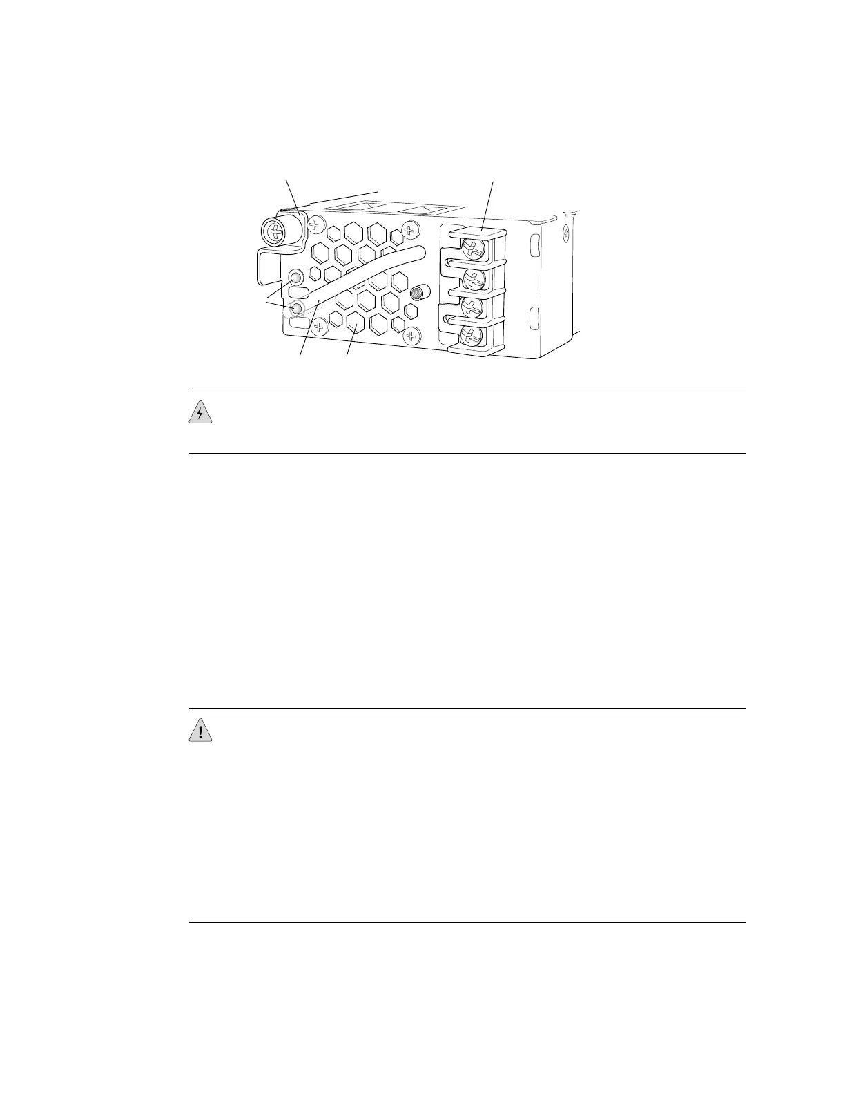
Figure 44: DC Power Supply in EX 3200 and EX 4200 Switches
LED-B
LED-A
Terminal blockLocking lever
LEDs
Handle Fan exhaust
A +
B +
A-
B-
g020202
WARNING: DC-powered EX 3200 and EX 4200 switches are intended for installation
only in a restricted access location.
Ensure that you have the following parts and tools available to connect DC power to
an EX 3200 or EX 4200 switch:
■ Electrostatic discharge (ESD) grounding strap
■ DC power source cables (12–14 AWG) with ring lug (Molex 190700067 or
equivalent) (not provided)
■ Phillips (+) screwdriver, number 2
Before you begin connecting DC power to an EX 3200 or EX 4200 switch:
■ Ensure that you have taken the necessary precautions to prevent ESD damage
(see “Preventing Electrostatic Discharge Damage” on page 138).
■ Ensure that you have connected the switch chassis to earth ground.
CAUTION: Before you connect power to the switch, a licensed electrician must attach
a cable lug to the grounding and power cables that you supply. A cable with an
incorrectly attached lug can damage the switch (for example, by causing a short
circuit).
To meet safety and electromagnetic interference (EMI) requirements and to ensure
proper operation, you must connect EX 3200 and EX 4200 switches to earth ground
before you connect them to power. For installations that require a separate grounding
conductor to the chassis, use the protective earthing terminal on the switch chassis
to connect to the earth ground. For instructions on connecting earth ground, see
“Connecting Earth Ground to an EX-series Switch” on page 78.
■ Install the power supply in the chassis. For instructions on installing a power
supply in an EX 3200 or EX 4200 switch, see “Installing a Power Supply in an
EX-series Switch” on page 107.
82 ■ Connecting DC Power to an EX 3200 or EX 4200 Switch
Complete Hardware Guide for EX 3200 and EX 4200 Switches
 Loading...