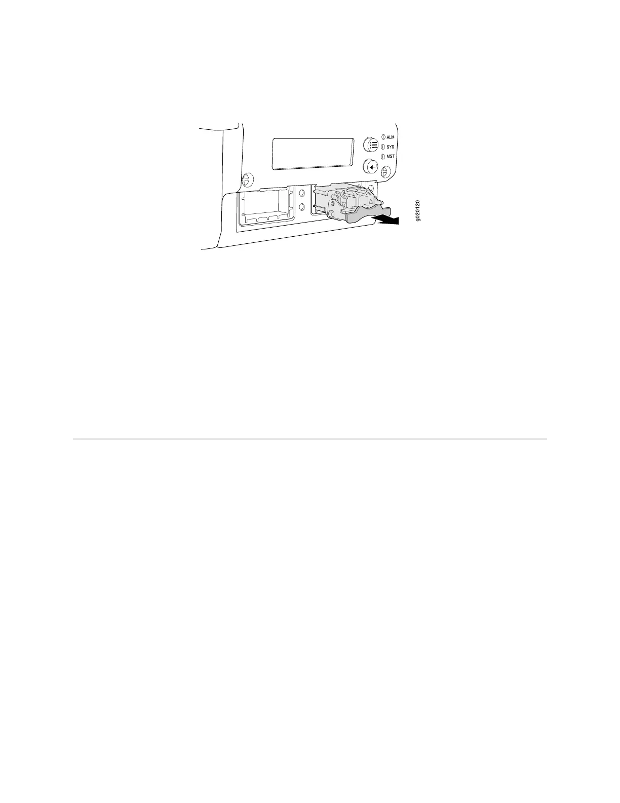
Figure 60: Removing an SFP or XFP Transceiver from an EX-series Switch
Related Topics ■ Installing an SFP or XFP Transceiver in an EX-series Switch on page 104
■ Installing an Uplink Module in an EX-series Switch on page 101
■ Optical Interface Support—EX 3200 and EX 4200 Switches on page 21
■ Installing and Removing EX-series Switch Hardware Components on page 100
■ Laser and LED Safety Guidelines and Warnings on page 143
■ Field-Replaceable Units in EX-series Switches on page 99
■ EX 3200 Switch—Front-Panel Description on page 9
■ EX 4200 Switch—Front-Panel Description on page 11
Installing a Power Supply in an EX-series Switch
The power supply in EX-series switches is a hot-removable and hot-insertable
field-replaceable unit (FRU) located on the rear panel.
Ensure you have the following tools and parts available to install a power supply in
an EX-series switch chassis:
■ Electrostatic discharge (ESD) grounding strap
■ Phillips (+) screwdriver, number 2
Ensure you understand how to prevent ESD damage (see “Preventing Electrostatic
Discharge Damage” on page 138).
To install a power supply in an EX-series switch (see Figure 61 on page 108):
1. Attach an electrostatic discharge (ESD) grounding strap to your bare wrist, and
connect the strap to the ESD point on the chassis.
2. Remove the power supply from its bag. Take care not to touch power supply
components, pins, leads, or solder connections.
3. Loosen the locking lever screw on the left front of the power supply by using a
Phillips (+) screwdriver, number 2.
4. Push down on the locking lever until it is in its lowest position.
Installing a Power Supply in an EX-series Switch ■ 107
Chapter 5: Replacing Hardware Components
 Loading...