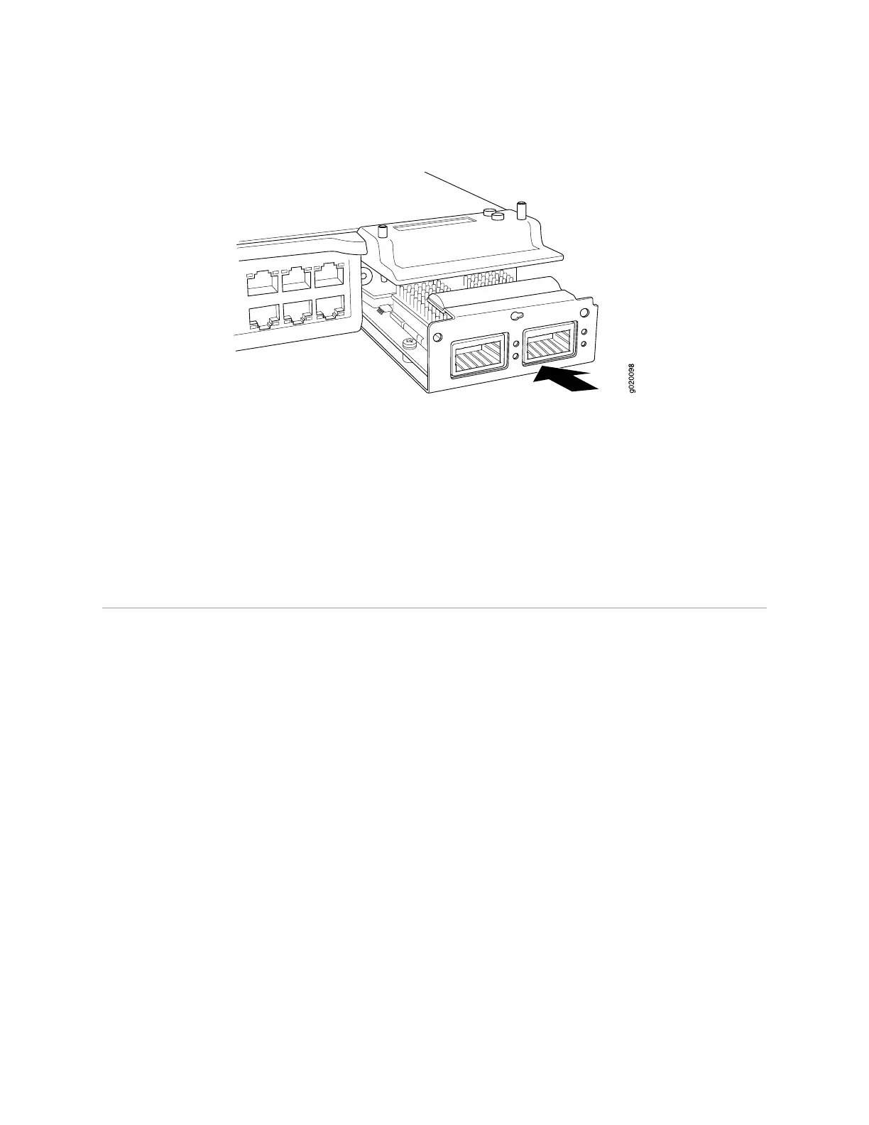
Figure 56: Installing an Uplink Module in an EX-series Switch
Related Topics ■ Removing an Uplink Module from an EX-series Switch on page 102
■ Installing and Removing EX-series Switch Hardware Components on page 100
■ Field-Replaceable Units in EX-series Switches on page 99
■ EX 3200 Switch—Front-Panel Description on page 9
■ EX 4200 Switch—Front-Panel Description on page 11
■ Optical Interface Support—EX 3200 and EX 4200 Switches on page 21
Removing an Uplink Module from an EX-series Switch
If your EX-series switch includes an optional field-replaceable unit (FRU) uplink
module, it is installed in the switch's front panel. The uplink module in an EX-series
switch is not hot-removable and hot-insertable.
Ensure you have the following tools and parts available to remove an uplink module
from an EX-series switch chassis:
■ Electrostatic discharge (ESD) grounding strap
■ Cross-head screwdriver (provided in the uplink module kit)
■ An electrostatic bag or antistatic mat
Ensure you understand how to prevent ESD damage (see “Preventing Electrostatic
Discharge Damage” on page 138).
To remove an uplink module from an EX-series switch:
1. Attach an electrostatic discharge (ESD) grounding strap to your bare wrist, and
connect the strap to the ESD point on the chassis.
2.
If the switch is on, power it off. Ensure that the AC OK LED on the power supply
is unlit.
102 ■ Removing an Uplink Module from an EX-series Switch
Complete Hardware Guide for EX 3200 and EX 4200 Switches
 Loading...