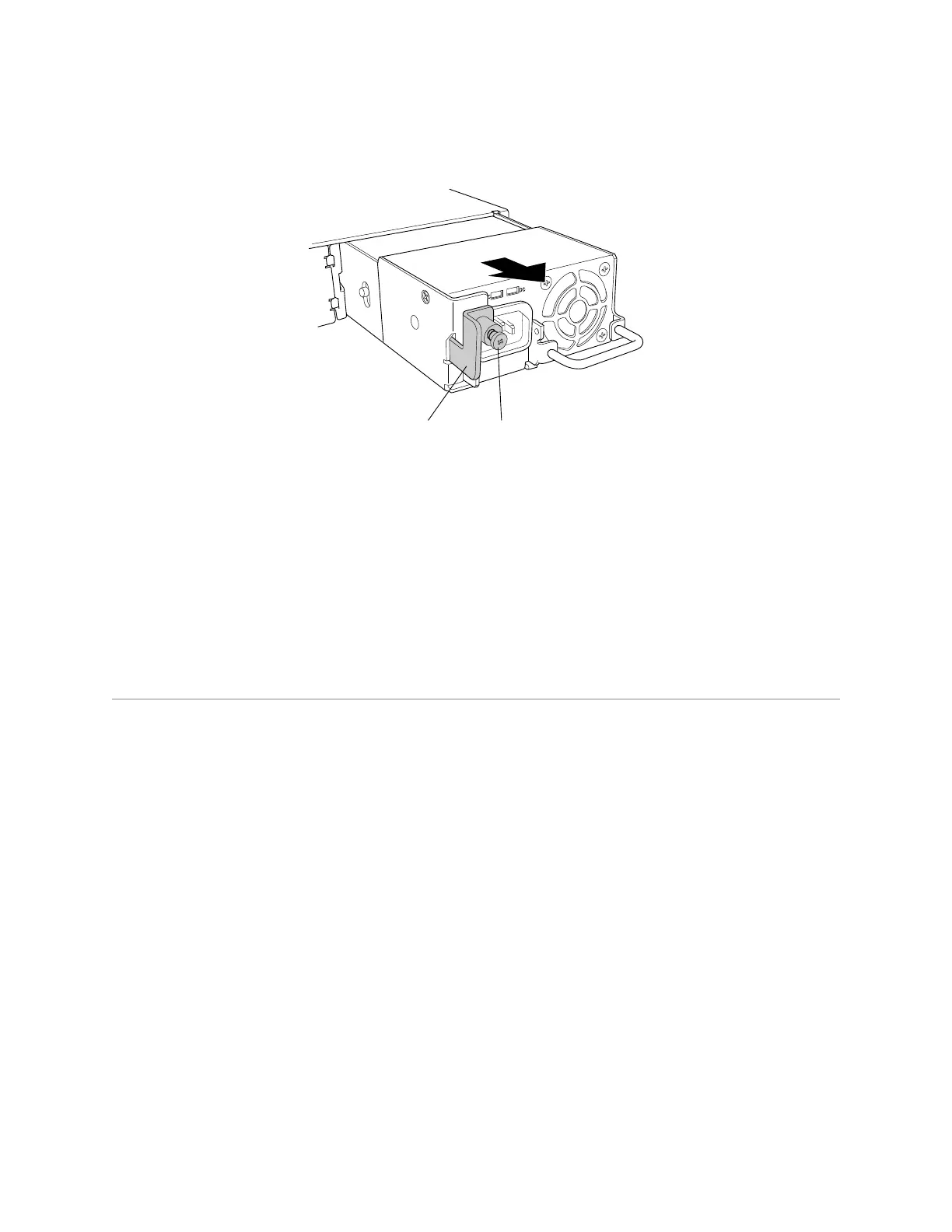
Figure 62: Removing a Power Supply from an EX-series Switch
Locking lever
g020090
Loosen captive screw.
Related Topics ■ Installing a Power Supply in an EX-series Switch on page 107
■ Installing and Removing EX-series Switch Hardware Components on page 100
■ Power Supply in EX 3200 and EX 4200 Switches on page 27
■ Field-Replaceable Units in EX-series Switches on page 99
■ AC Power, Connection, and Power Cord Specifications on page 56
■ EX 3200 Switch—Rear-Panel Description on page 10
■ EX 4200 Switch—Rear-Panel Description on page 12
Installing a Fan Tray in an EX-series Switch
EX-series switches have a single field-replaceable unit (FRU) fan tray on the rear
panel. The fan tray is hot-removable and hot-insertable FRU: you can remove and
replace it while the switch is functioning without turning off power to the switch or
disrupting switch functions.
Ensure you have the following tools and parts available to install a fan tray in an
EX-series switch chassis:
■ Electrostatic discharge (ESD) grounding strap
■ Phillips (+) screwdriver, number 2
Ensure you understand how to prevent ESD damage (see “Preventing Electrostatic
Discharge Damage” on page 138).
To install a fan tray in an EX-series switch chassis (see Figure 63 on page 111 and
Figure 64 on page 111):
1. Attach an electrostatic discharge (ESD) grounding strap to your bare wrist, and
connect the strap to the ESD point on the chassis.
110 ■ Installing a Fan Tray in an EX-series Switch
Complete Hardware Guide for EX 3200 and EX 4200 Switches
 Loading...