Figure 52: Ethernet Cable Connector
Related Topics ■ Connecting an EX-series Switch to a Network for Out-of-Band
Management on page 85
■ EX 3200 Switch—Rear-Panel Description on page 10
■ EX 4200 Switch—Rear-Panel Description on page 12
■ EX-series Switch—Console Port Connector Pinout Information on page 34
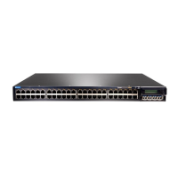
Connecting a Virtual Chassis Cable to an EX 4200 Switch
EX 4200 switches have two virtual chassis ports on the rear panel. You can use the
virtual chassis ports to interconnect up to 10 EX 4200 switches, enabling them to
operate as a unified single high bandwidth switch. To see illustrations of a few virtual
chassis cabling configuration examples, see “Virtual Chassis Cabling Configuration
Examples” on page 72.
Ensure you have the following tools and parts available to connect a virtual chassis
cable to an EX 4200 switch:
■ Electrostatic discharge (ESD) grounding strap
■ Cross-head screwdriver
Ensure you understand how to prevent ESD damage (see “Preventing Electrostatic
Discharge Damage” on page 138).
To connect a virtual chassis cable to an EX-series switch (see Figure 53 on page 89):
1. Attach an electrostatic discharge (ESD) grounding strap to your bare wrist, and
connect the strap to the ESD point on the chassis.
2. Remove the virtual chassis cable from its bag. Take care not to touch module
components, pins, leads, or solder connections.
3. Using both hands, place the virtual chassis cable connector in the empty virtual
chassis port and slide it in gently until it is fully seated.
4. Slide the locking cover over the virtual chassis cable connector.
5. Tighten the screws on the locking cover by using the cross-head screwdriver.
88 ■ Connecting a Virtual Chassis Cable to an EX 4200 Switch
Complete Hardware Guide for EX 3200 and EX 4200 Switches
 Loading...