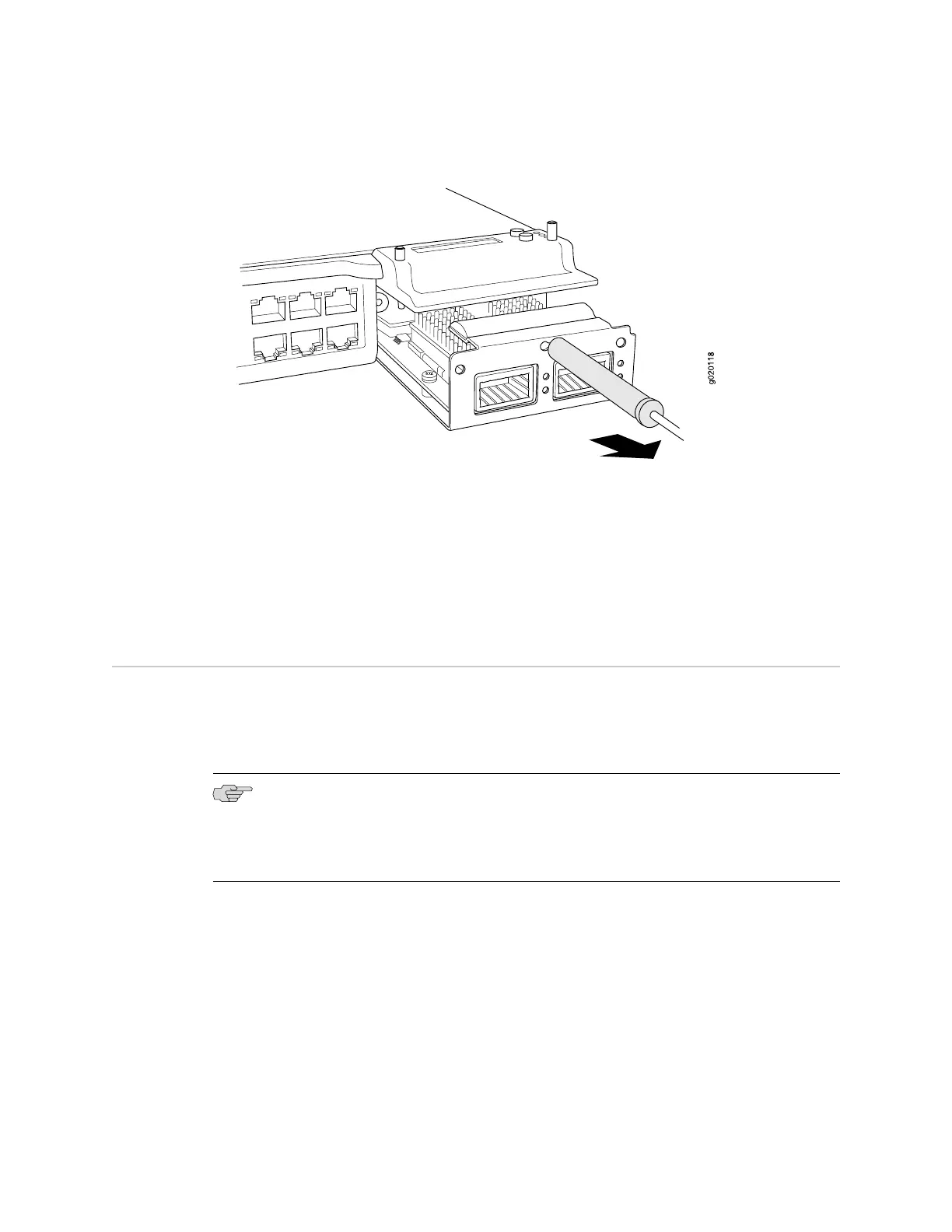
Figure 58: Removing an Uplink Module from an EX-series Switch
Related Topics ■ Installing an Uplink Module in an EX-series Switch on page 101
■ Installing and Removing EX-series Switch Hardware Components on page 100
■ Field-Replaceable Units in EX-series Switches on page 99
■ EX 3200 Switch—Front-Panel Description on page 9
■ EX 4200 Switch—Front-Panel Description on page 11
Installing an SFP or XFP Transceiver in an EX-series Switch
EX-series switches have a field-replaceable unit (FRU) uplink module on the front
panel. You can install four SFP transceivers in the SFP uplink module and two XFP
transceivers in the XFP uplink module. The SFP and XFP transceivers in EX-series
switches are hot-removable and hot-insertable.
NOTE: If you insert a transceiver in an SFP uplink module installed in an EX 3200
switch, a corresponding network port from the last four ports is disabled. For example,
if you insert an SFP transceiver in ge-0/1/3, ge-0/0/23 is disabled. The disabled port
is not listed in the output of show interface commands.
Ensure that you understand safe handling of lasers (see “Laser and LED Safety
Guidelines and Warnings” on page 143) and have the following tools and parts available
to install an SFP or XFP transceiver in an EX-series switch chassis:
■ Electrostatic discharge (ESD) grounding strap
■ A rubber safety cap for the transceiver
Ensure you understand how to prevent ESD damage (see “Preventing Electrostatic
Discharge Damage” on page 138).
104 ■ Installing an SFP or XFP Transceiver in an EX-series Switch
Complete Hardware Guide for EX 3200 and EX 4200 Switches
 Loading...