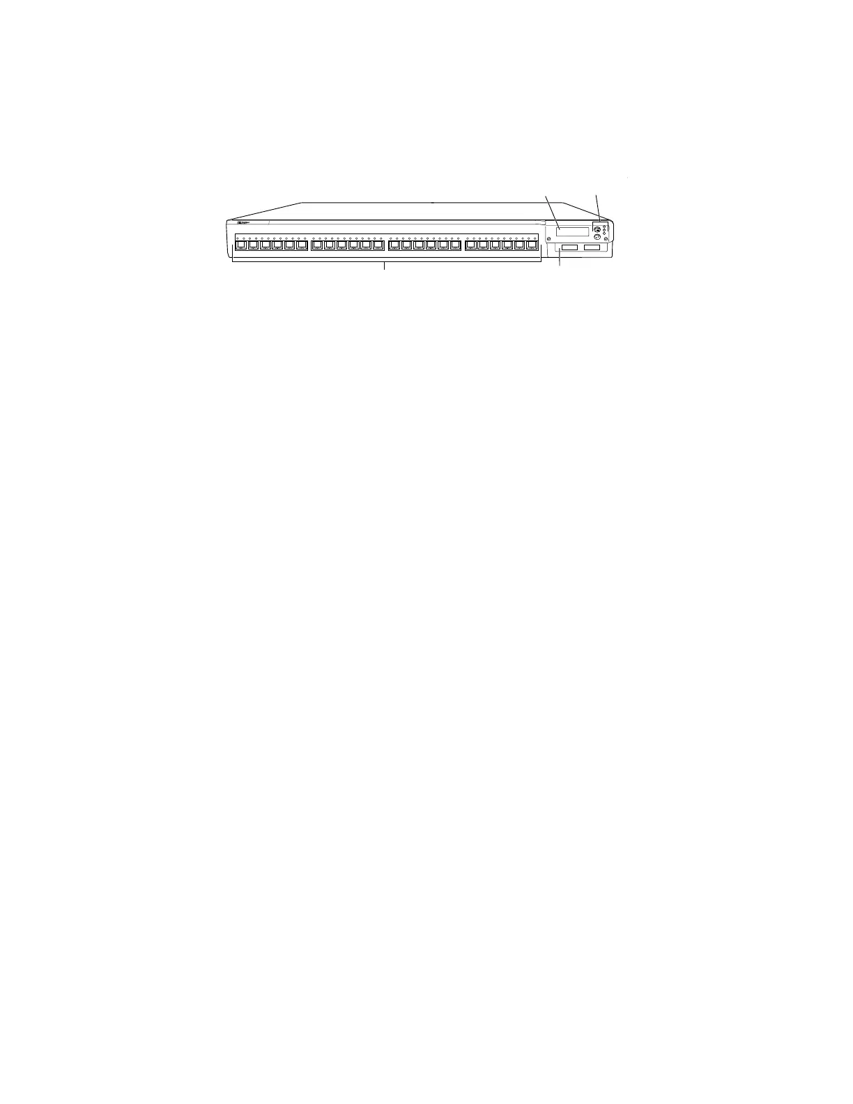
Figure 6: EX 4200-24F Switch with 24 SFP Ports
EX 4200
g020067
0 1 2 3 4 5 6 7 8 9 10 11 12 13 14 15 16 17 18 19 20 21 22 23
Network ports
LCD panel
Uplink module
LCD buttons
and LEDs
Related Topics ■ EX 4200 Switch—Front-Panel LEDs on page 14
■ EX-series Switch—LCD on page 24
■ EX-series Switch—Network Port LEDs on page 15
■ Installing and Removing EX-series Switch Hardware Components on page 100
■ Installing an Uplink Module in an EX-series Switch on page 101
■ Removing an Uplink Module from an EX-series Switch on page 102
EX 4200 Switch—Rear-Panel Description
The rear panel of the EX 4200 switch consists of the following components:
■ Fan tray
■ Virtual chassis ports (VCPs)
■ USB port
■ Temperature shutdown LED
■ Management Ethernet port
■ Console port
■ ESD point
■ Power supply
Figure 7 on page 13 shows the rear panel of an EX 4200 switch. All switches in the
EX 4200 series have the same rear panel. The 320 W power supply is flush with the
chassis. The 600 W power supply and 930 W power supply extend out of the chassis
by 2.25 inches. Power cord retainer clips extend out of the power supply by 3 inches.
12 ■ EX 4200 Switch—Rear-Panel Description
Complete Hardware Guide for EX 3200 and EX 4200 Switches
 Loading...