■ Cooling System in an EX 3200 Switch on page 30
■ Power Supply in EX 3200 and EX 4200 Switches on page 27
■ Preventing Electrostatic Discharge Damage on page 138
■ Connecting Earth Ground to an EX-series Switch on page 78
■ Installing and Removing EX-series Switch Hardware Components on page 100
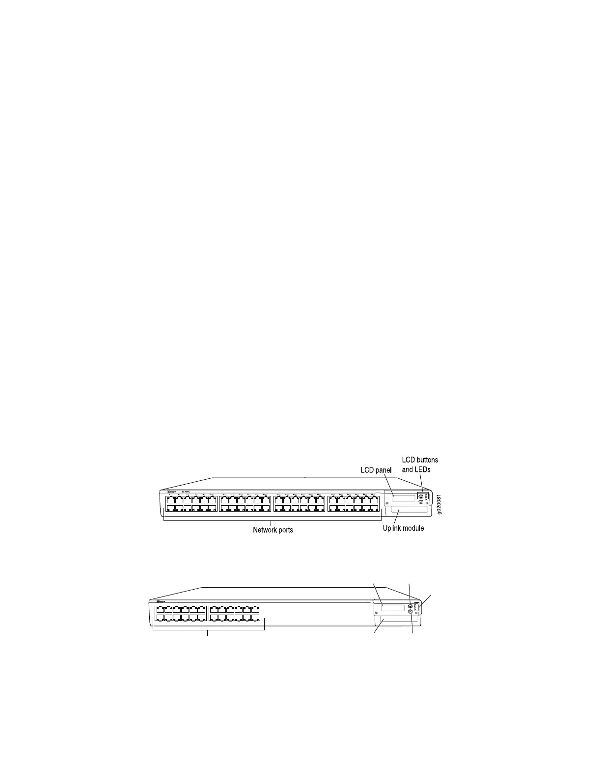
EX 4200 Switch—Front-Panel Description
The front panel of the EX 4200 switch consists of the following components:
■ Network ports—depending on the switch model, either of:
■ 10/100/1000 Base-T Gigabit Ethernet ports, some or all of which are enabled
for Power over Ethernet (PoE)
■ 100Base-FX/1000Base-X SFP transceivers for use with fiber-optic connections
■ Optional uplink module provides SFP or XFP ports
■ LCD panel and the LCD navigation buttons
■ Front-panel LEDs
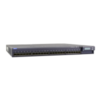
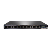
Figure 4 on page 11 shows the front panel of an EX 4200 switch with 48 Gigabit
Ethernet ports. Figure 5 on page 11 shows the front panel of an EX 4200 switch with
24 Gigabit Ethernet ports. Figure 6 on page 12 shows the front panel of an
EX 4200-24F switch with 24 SFP ports for use with fiber-optic connectors.
Figure 4: EX 4200 Switch with 48 Gigabit Ethernet Ports
Figure 5: EX 4200 Switch with 24 Gigabit Ethernet Ports
EX 3200
0
1
2
3
4
5
6
7
8
9
10
11
12
13
14
15
16
17
18
19
20
21
22
23
g020054
Network ports
LCD panel
Uplink module
Menu button
Enter button
LEDs
ALM
SYS
MST
EX 4200 Switch—Front-Panel Description ■ 11
Chapter 1: Switch Overview
 Loading...