Table 7 on page 16 describes LED 2, which indicates the administrative status
(enabled or disabled), duplex mode, PoE status, or speed, of the network ports. From
the Idle menu of the LCD, use the Enter button on the LCD panel to toggle between
the ADM, DPX, POE, and SPD indicators.
Table 7: EX-series Switch—Network Port LEDs–LED 2
State and DescriptionLCD IndicatorLED
Indicates the administrative status (enabled or disabled). The
status indicators are:
■
Green—Port is enabled
■
Unlit—Port is disabled
LED: ADMLED 2
Indicates the duplex mode. The status indicators are:
■
Green—Port is set to full-duplex mode
■
Unlit—Port is set to half-duplex mode
LED: DPX
Indicates the PoE status. The status indicators are:
■
Green—PoE is enabled on the port
■
Yellow—PoE failure; the power limit for the PoE port is
exceeded or the device connected to the port is not PoE
compliant
■
Unlit—PoE is not enabled on the port
LED: POE
Indicates the speed. The status indicators are:
■
One blink per second—10 Mbps
■
Two blinks per second—100 Mbps
■
Three blinks per second—1000 Mbps
LED: SPD
Related Topics ■ EX-series Switch—SFP Uplink Module Port LEDs on page 18
■ EX-series Switch—XFP Uplink Module Port LEDs on page 19
■ EX 3200 Switch—Front-Panel Description on page 9
■ EX 4200 Switch—Front-Panel Description on page 11
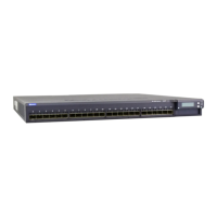
Uplink Modules in an EX 3200 or EX 4200 Switch
Optional uplink modules are available for all EX 3200 and EX 4200 models. Uplink
modules provide either two 10-gigabit small form-factor pluggable (XFP) transceivers
or four 1-gigabit small form-factor pluggable (SFP) transceivers. You can use these
ports to connect an access switch to a distribution switch or to interconnect member
switches of a virtual chassis across multiple wiring closets.
Figure 11 on page 17 shows the SFP uplink module:
16 ■ Uplink Modules in an EX 3200 or EX 4200 Switch
Complete Hardware Guide for EX 3200 and EX 4200 Switches
 Loading...