5. Using both hands, place the power supply in the power supply slot on the rear
panel of the switch and slide it in until it is fully seated.
NOTE: The handle on the 320 W power supply used in an EX-series switch is at the
bottom while the handle on the 600 W or 930 W power supply used in an EX-series
switch is at the top.
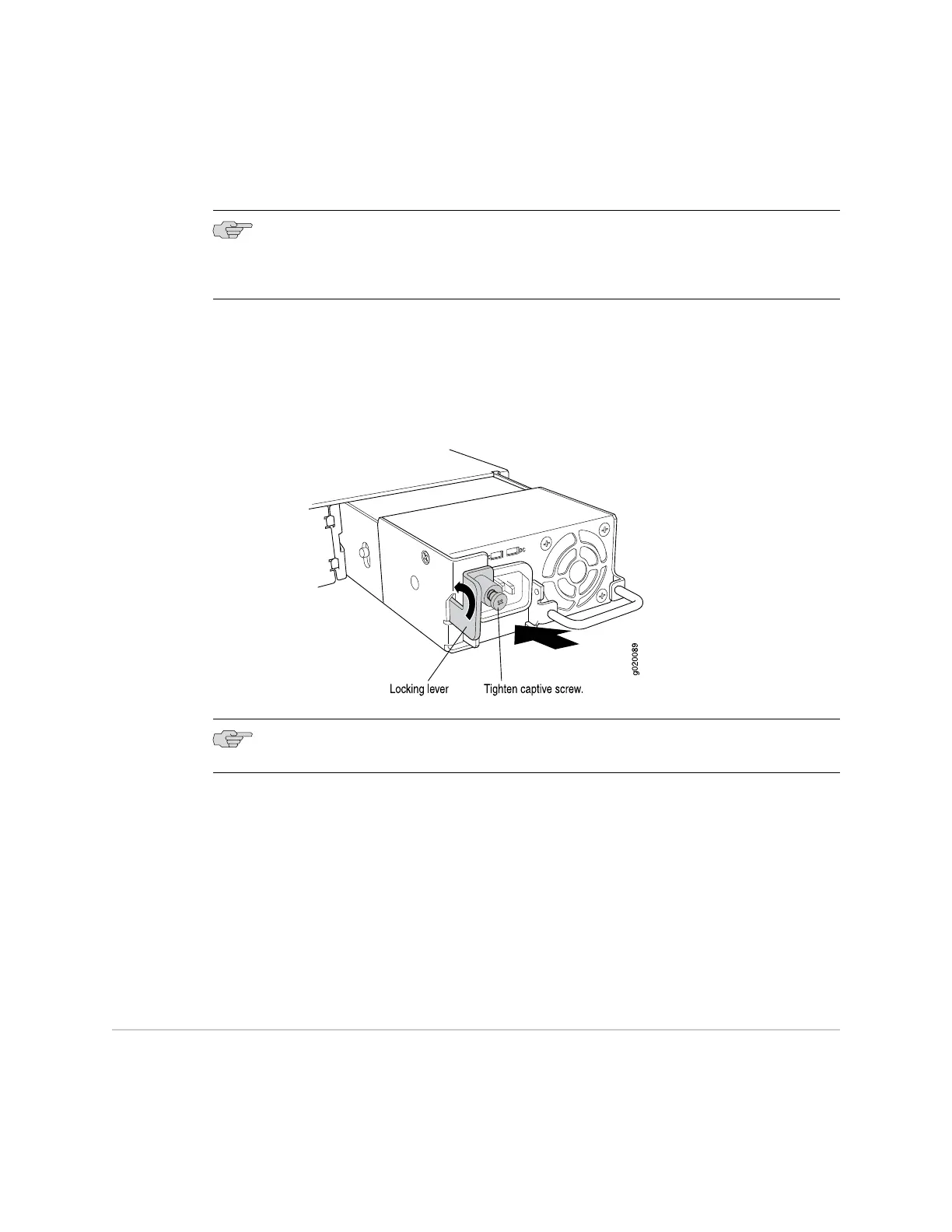
6. Push the locking lever up to its highest position (this action might pull the power
supply in).
7. Tighten the locking lever screw by using a Phillips (+) screwdriver, number 2.
Figure 61: Installing a Power Supply in an EX-series Switch
NOTE: Each power supply must be connected to a dedicated power source outlet.
Related Topics ■ Removing a Power Supply from an EX-series Switch on page 108
■ Installing and Removing EX-series Switch Hardware Components on page 100
■ Power Supply in EX 3200 and EX 4200 Switches on page 27
■ Field-Replaceable Units in EX-series Switches on page 99
■ AC Power, Connection, and Power Cord Specifications on page 56
■ EX 3200 Switch—Rear-Panel Description on page 10
■ EX 4200 Switch—Rear-Panel Description on page 12
Removing a Power Supply from an EX-series Switch
The power supply in EX-series switches is a hot-removable and hot-insertable
field-replaceable unit (FRU) located on the rear panel.
108 ■ Removing a Power Supply from an EX-series Switch
Complete Hardware Guide for EX 3200 and EX 4200 Switches
 Loading...