3. Loosen the screws that secure the flip-up door covering the uplink module slot
on the front panel of the chassis by using the cross-head screwdriver provided
with the uplink module kit and flip the door upward.
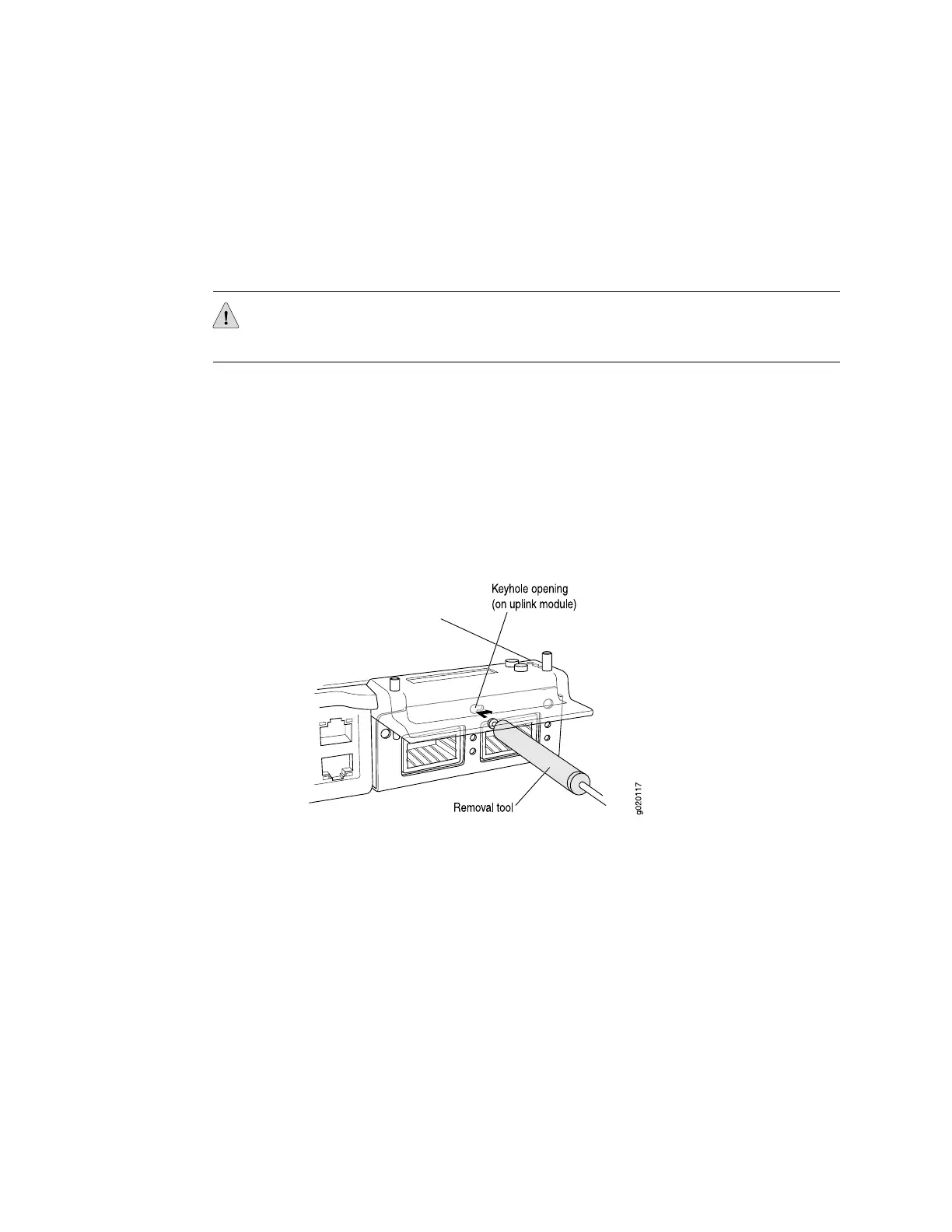
4. Insert the ball end of the screwdriver in the keyhole on the front panel of the
uplink module and slide the screwdriver to the narrow part of the keyhole (see
Figure 57 on page 103).
CAUTION: Ensure the screwdriver does not slip out of the keyhole when you pull
the uplink module out of the switch chassis.
5. Using both hands, gently pull the screwdriver to slide the uplink module halfway
out of the chassis (see Figure 58 on page 104).
6. Place one hand under the uplink module to support it and slide it completely out
of the chassis.
7. Slide the screwdriver out of the keyhole.
8. Place the uplink module in the electrostatic bag or on the antistatic mat.
Figure 57: Sliding the Screwdriver to the Narrow Part of the Keyhole
Removing an Uplink Module from an EX-series Switch ■ 103
Chapter 5: Replacing Hardware Components
 Loading...