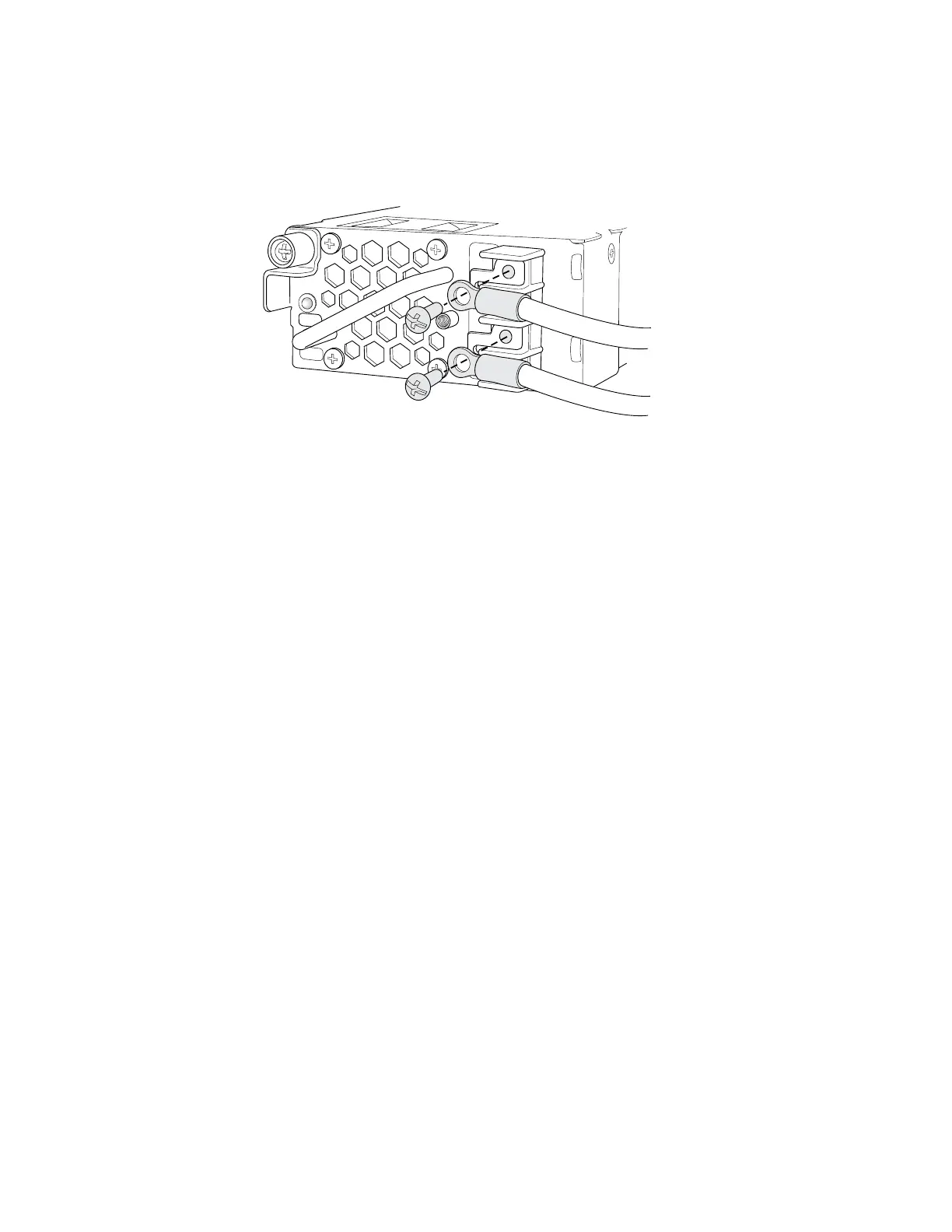
Figure 46: Securing Ring Lugs to the Terminals on the DC Power Supply in EX 3200
and EX 4200 Switches
A +
B +
A-
B-
LED-B
LED-A
g020203
7. Replace the terminal block cover and secure it using the screw. Use the
Phillips (+) screwdriver, number 2 to tighten the screw.
8. Close the input circuit breaker.
9. Verify that the LEDs on the power supply are lit green and are on steadily.
“DC Power Supply LEDs in EX 3200 and EX 4200 Switches” on page 32 describes
the LEDs on the DC power supplies in EX 3200 and EX 4200 switches.
Related Topics ■ Connecting and Configuring the EX-series Switch (CLI Procedure) on page 91
■ Connecting and Configuring the EX-series Switch (J-Web Procedure) on page 92
■ Power Supply in EX 3200 and EX 4200 Switches on page 27
■ Connecting AC Power to an EX 3200 or EX 4200 Switch on page 79
Connecting an EX-series Switch to a Network for Out-of-Band Management
EX-series switches have an out-of-band management port with an RJ-45 connector
on the rear panel. If you need to monitor and manage an EX-series switch using a
dedicated management channel, you can use the out-of-band management port to
connect the EX-series switch to the management device.
Ensure you have an Ethernet cable with an RJ-45 connector available. One such cable
is provided with the switch. Figure 49 on page 88 shows the RJ-45 connector of the
Ethernet cable supplied with the switch.
To connect an EX-series switch to a network for out-of-band management (see
Figure 47 on page 86 and Figure 48 on page 86):
1. Connect one end of the Ethernet cable to the management port (labelled MGMT)
on the rear panel of the EX-series switch.
2. Connect the other end of the Ethernet cable to the network device.
Connecting an EX-series Switch to a Network for Out-of-Band Management ■ 85
Chapter 3: Installing the Switch
 Loading...