Before mounting the switch on a wall:
•
Verify that the site meets the requirements described in “Site Preparation Checklist
for EX2200 Switches” on page 51.
•
Read “General Safety Guidelines and Warnings” on page 155, with particular attention
to “Chassis Lifting Guidelines for EX2200 Switches” on page 166.
Ensure that you have the following parts and tools available:
•
2 wall-mount brackets (provided in the wall-mount kit)
•
1 wall-mount baffle (provided in the wall-mount kit)
•
12 wall-mount bracket screws (provided in the wall-mount kit)
•
6 mounting screws (8-32 x 1.25 in. or M4 x 30 mm) (not provided)
•
Hollow wall anchors rated to support up to 75 lb (34 kg) if you are not screwing the
screws directly into wall studs (not provided)
•
Phillips (+) screwdriver, number 2
To mount one or two switches on a wall:
1. Remove the switch from the shipping carton (see “Unpacking an EX2200 Switch” on
page 72).
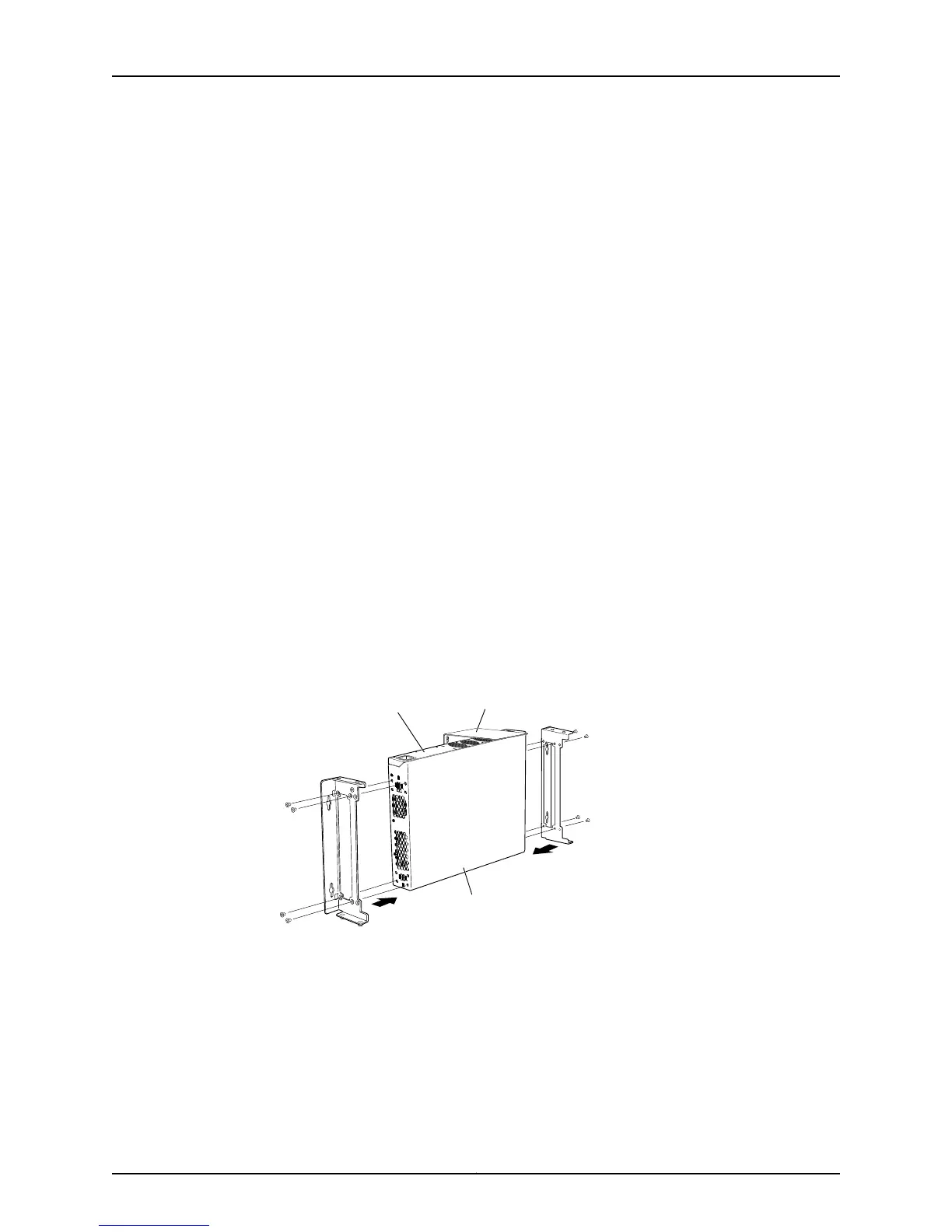
2. Attach the wall-mount brackets to the sides of the chassis using four wall-mount
bracket screws on each side, as shown in Figure 34 on page 89.
Figure 34: Attaching Wall-Mount Brackets to a Switch Chassis
g027022
Front panel
Rear panel
Baffle for PoE Models
(EX2200-24P and EX2200-48P)
3. If you are mounting two switches together, align the second switch on top of the first
and attach it to the mounting brackets using two additional wall-mount bracket
screws on each side. (Figure 36 on page 91 shows two aligned switches.)
4. Install four mounting screws in the wall for the wall-mount brackets (and two more
for the baffle if you are installing a switch that supports PoE) as shown in Figure 35
on page 90:
89Copyright © 2011, Juniper Networks, Inc.
Chapter 8: Installing the Switch

 Loading...