•
Use hollow wall anchors rated to support up to 75 lb (34 kg) if you are not inserting
the mounting screws directly into wall studs.
•
Turn the screws only part way in, leaving about 1/4 in. (6 mm) distance between
the head of the screw and the wall.
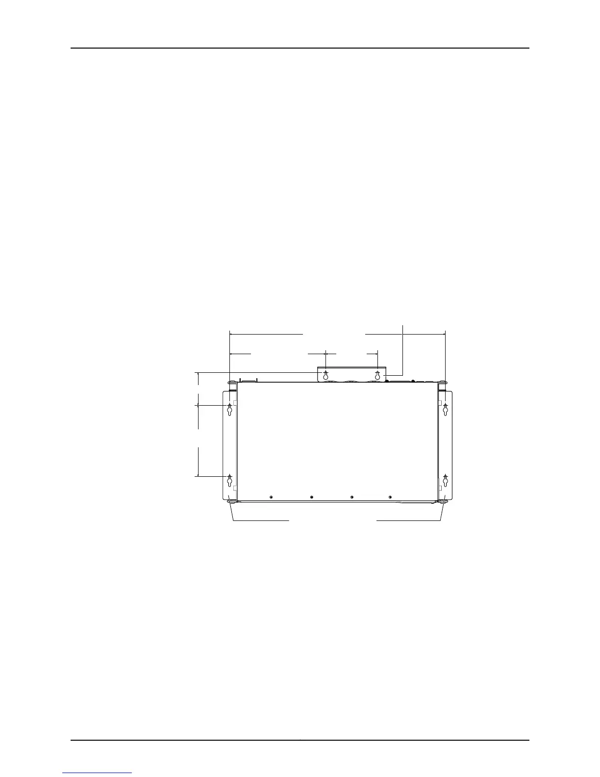
a. Install screw A.
b. Install screw B 18.68 in. (47.4 cm) from screw A on a level line.
c. Install screw C 5.98 in. (15.2 cm) on a plumb line down from screw A and screw D
5.98 in. down from screw B.
d. For PoE models, install screw E 2.76 in. (7 cm) up from and 8.32 in. (21.1 cm) to the
right of screw A.
e. For PoE models, install screw F 4.49 in. (11.4 cm) to the right of screw E.
Figure 35: Measurements for Installing Mounting Screws
18.68 in. (47.4 cm)
Front
Rear
A
E F
C
B
D
Side wall-mount brackets
8.32 in. (21.1 cm)
4.49 in.
(11.4 cm)
5.98 in.
(15.2 cm)
2.76 in (7 cm)
g021067
Baffle for PoE Models
(EX2200-24P and EX2200-48P)
5. Lift the unit (one switch or two) by grasping each side, and hang the unit by attaching
the brackets to the mounting screws as shown in Figure 36 on page 91.
6. For PoE models, install the baffle by attaching it to screws E and F.
7. Tighten all mounting screws.
Copyright © 2011, Juniper Networks, Inc.90
Complete Hardware Guide for EX2200 Ethernet Switches

 Loading...