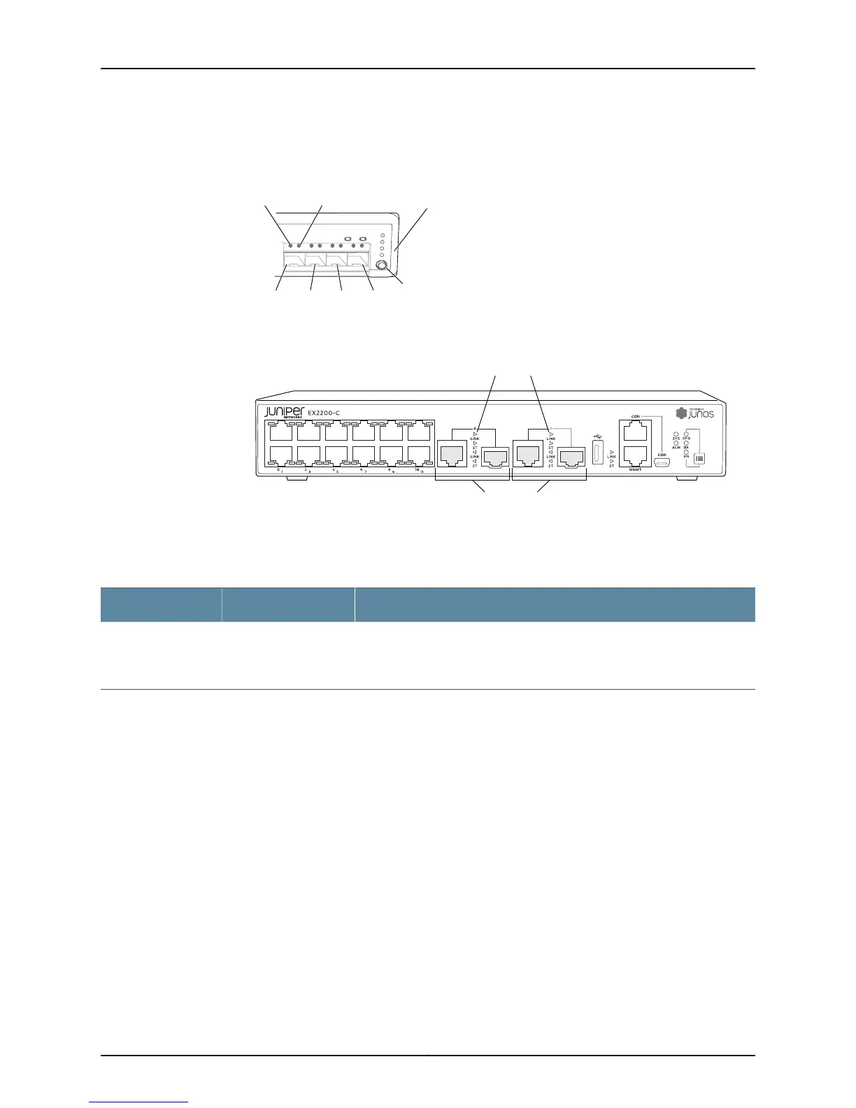
Figure 10: LEDs on the Uplink Ports and Port Status Mode LEDs in an
EX2200 Switch Except the EX2200-C Switch Model
g027007
0 1 2
SYS
ALM
SPD
DX
EN
POE
3
Port 1 Port 2 Port 3
Mode
button
Link/Activity
LED
Status
LED
Port 0
Port status
mode LEDs
Figure 11: Port status mode LEDs of the Dual-purpose uplink Ports of an
EX2200-C Switch
g021154
Dual-purpose
uplink ports
Port status mode LEDs
Table 5 on page 15 describes the Link/Activity LED.
Table 5: Link/Activity LED on the Network Ports and Uplink Ports in EX2200 Switches
State and DescriptionColorLED
•
Blinking—The port and the link are active, and there is link activity.
•
On steadily—The port and the link are active, but there is no link activity.
•
Off—The port is not active.
GreenLink/Activity
In Figure 9 on page 14, Figure 10 on page 15, and Figure 11 on page 15 show the LEDs that
indicate the status of one of the four port parameters—speed, duplex mode, administrative
status, and Power over Ethernet (PoE) status. Use the mode button below the POE LED
on the far right side of the front panel to toggle the Status LED to show the different port
parameters. You can tell which port parameter is indicated by the Status LED by seeing
which port status mode LED (SPD, DX, EN, and POE) is lit. (See Figure 10 on page 15).
Table 6 on page 16 describes the Status LED.
15Copyright © 2011, Juniper Networks, Inc.
Chapter 2: Component Descriptions

 Loading...