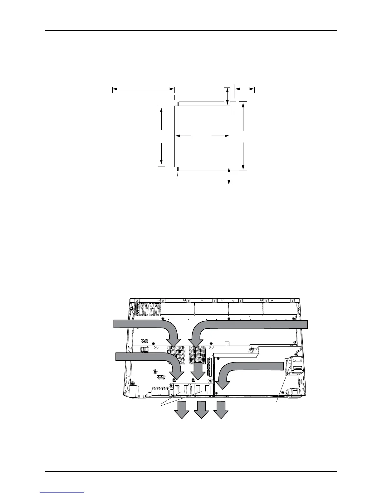
Figure 17: Clearance Requirements for Airflow and Hardware Maintenance
for EX2200-C Switch Models
g021163
Mounting bracket
6" (15.2 cm)
for airflow
RearFront
7.18"
(26.9 cm)
8.7"
(22.1 cm)
Clearance
required for
maintenance
Clearance required
for maintenance
24" (61 cm)
6" (15.2 cm)
6" (15.2 cm)
for airflow
19"
(48.2 cm)
The power cord retainer clips extend out of the rear of the chassis by 3 in.
•
Allow at least 6 in. (15.2 cm) of clearance on the side between devices that have fans
or blowers installed. Allow 2.8 in. (7 cm) between the side of the chassis and any
non-heat-producing surface such asa wall. For the cooling system to function properly,
the airflow around the chassis must be unrestricted.
Figure 18 on page 61 shows the airflow in PoE models of EX2200 switches, except for
EX2200-C models. Figure 19 on page 62 shows the airflow non-PoE models of EX2200
switches, except for EX2200-C models.
Figure 18: Airflow Through PoE Models of EX2200 Switches Except
EX2200-C Switch Models
g027008
Chassis rear
Chassis front
Fans Fan
61Copyright © 2011, Juniper Networks, Inc.
Chapter 5: Mounting and Clearance Requirements

 Loading...