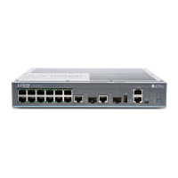
3. Connect one end of the cable to the console port (labeled CON or CONSOLE) on the
switch.
For the location of the console port on different EX Series switches:
•
See “EX2200 Switches Hardware Overview” on page 3.
•
See Rear Panel of an EX3200 Switch.
•
See Rear Panel of an EX3300 Switch.
•
See Rear Panel of an EX4200 Switch.
•
See Front Panel of an EX4500 Switch.
•
See Switch Fabric and Routing Engine (SRE) Module in an EX8208 Switch.
•
See Routing Engine (RE) Module in an EX8216 Switch.
4. Connect the other end of the cable to the RJ-45 to DB-9 serial port adapter supplied
with your switch.
5. Connect the serial port adapter to the DB-9 female to DB-25 male adapter or other
adapter appropriate for your modem.
6. Plug the modem adapter into the DB-25 connector on the modem.
7. Connect one end of the phone cableto the modem and the other end to your telephone
network.
8. Turn on the power to your modem.
9. Power on the switch.
Related
Documentation
Connecting an EX Series Switch to a Management Console on page 115•
• Console Port Connector Pinout Information for an EX Series Switch on page 23
Connecting a Fiber-Optic Cable to an EX Series Switch
EX Series switches have field-replaceable unit (FRU) optical transceivers to which you
can connect fiber-optic cables.
Before you begin connecting a fiber-optic cable to an optical transceiver installed in an
EX Series switch, ensure that you have taken the necessary precautions for safe handling
of lasers (see “Laser and LED Safety Guidelines and Warnings for EX Series Switches”
on page 161).
121Copyright © 2011, Juniper Networks, Inc.
Chapter 10: Connecting the Switch

 Loading...