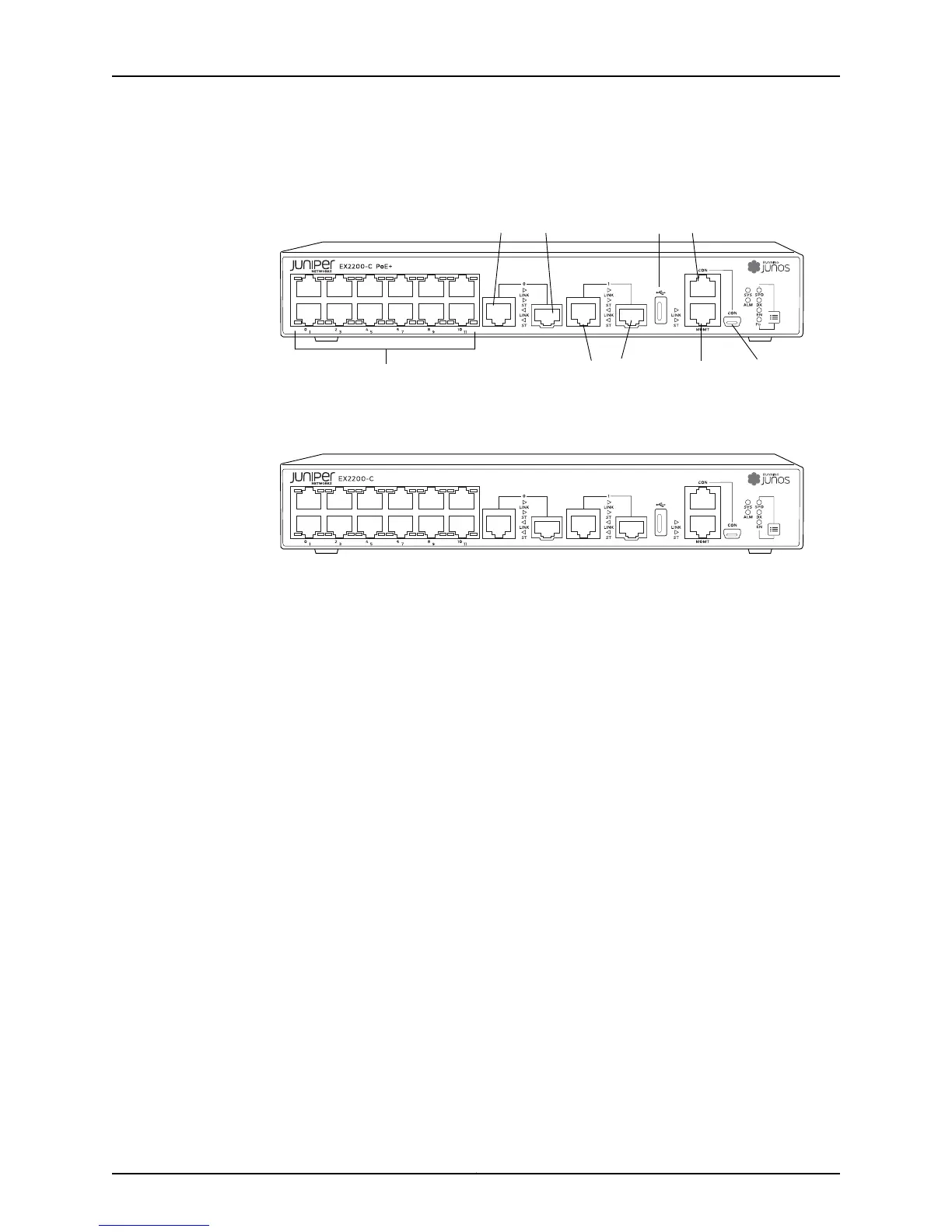
Figure 3: Front Panel of an EX2200-C Switch with 12 Gigabit Ethernet
Ports (PoE+)
g021150
Network ports
Dual-purpose
uplink ports 0
Dual-purpose
uplink ports 1
Console
port
USB
port
Mini USB
port
Management
port
Figure 4: Front Panel of an EX2200-C Switch with 12 Gigabit Ethernet
Ports (non-PoE)
Rear Panel of an EX2200 Switch
The rear panel of the EX2200 switch except the EX2200-C switch models consists of
the following components:
•
Management Ethernet port
•
USB port
•
Console port
•
Protective earthing terminal
•
ESD point
•
Air exhaust
•
Serial number ID label
•
AC power cord inlet or DC power terminals
Figure 5 on page 8 shows the rear panel of an EX2200 switch with an AC power supply.
All EX2200 switches except the EX2200-C switch model have three exhaust openings
on the rear panel. The two exhaust openings on the left have fans behind them and are
open. The exhaust opening on the right is open on Power over Ethernet (PoE) models
and closed on non-PoE models. On PoE models, this opening exhausts the air from the
fan at the air intake for the power supply on the side panel.
The power cord retainer clips extend out of the chassis by 3 in.
7Copyright © 2011, Juniper Networks, Inc.
Chapter 1: EX2200 Switch Overview

 Loading...