EasyManuals Logo
Home>Juniper>Switch>EX2300-C

Juniper EX2300-C Hardware Guide

Juniper EX2300-C
294 pages
To Next Page IconTo Next Page
To Previous Page IconTo Previous Page
Page #161 background imageLoading...
Page #161 background image
To mount the switch on four posts of a rack:
1. Remove the switch from the shipping carton (see “Unpacking an EX2300 Switch” on
page 123).
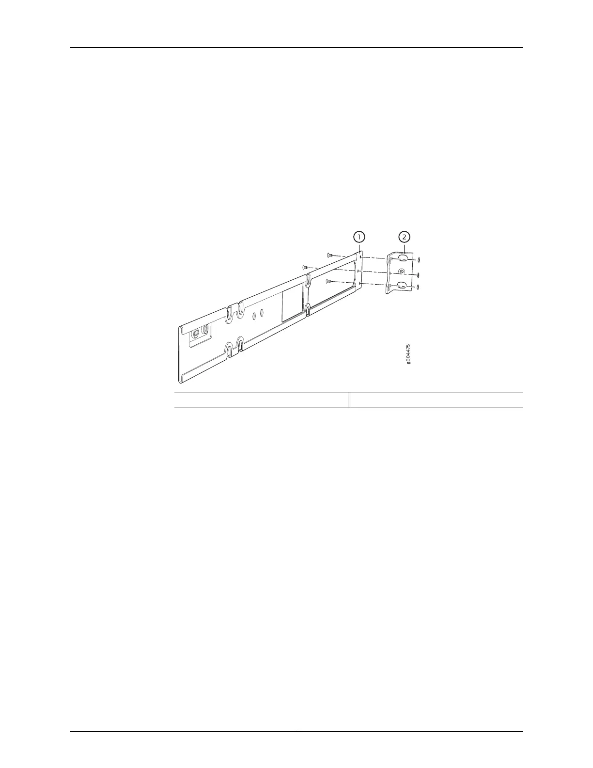
2. Attach the front-mounting brackets (either the flush or the 2-in.-recess brackets) to
the side mounting-rails by using 6 Phillips 4-40 flat-head mounting screws. See
Figure 38 on page 139.
Figure 38: Attaching the Front-Mounting Bracket to the Side Mounting-Rail
2—1— Front-mounting bracketSide mounting-rail
3. Place the switch on a flat, stable surface.
4. Align the side mounting-rails along the side panels of the switch chassis. Align the
two holes in the rear of the side mounting-rails with the two holes on the rear of the
side panel.
5. Insert the Phillips 4x6-mm flat-head mounting screws into the two aligned holes and
tighten the screws. Ensure that the two holes in the rear of the side mounting-rails
are aligned with the remaining two holes in the side panel. See Figure 39 on page 139.
6. Insert the Phillips 4x6-mm flat-head mounting screws into the remaining two holes
in the side mounting-rails and tighten the screws.
7. Have one person grasp both sides of the switch, lift the switch, and position it in the
rack, aligning the side mounting-rail holes with the threaded holes in the front post
of the rack. Align the bottom hole in both the front-mounting brackets with a hole in
each rack rail, making sure that the chassis is level. See Figure 40 on page 140.
139Copyright © 2017, Juniper Networks, Inc.
Chapter 12: Installing the Switch

Table of Contents

Other manuals for Juniper EX2300-C

Questions and Answers:

Question and Answer IconNeed help?

Do you have a question about the Juniper EX2300-C and is the answer not in the manual?

Juniper EX2300-C Specifications

General IconGeneral
SafetyUL-UL60950-1, C-UL CAN/CSA 22.2 No.60950-1, TUV/GS EN 60950-1, CB-IEC60950-1, EN 60825-1
Form factor1U
Product colorBlack
Rack mountingYes
Electromagnetic compatibilityFCC 47CFR 15 A, EN 55022 A, ICES-003 A, VCCI A, AS/NZS CISPR 22 A, EN 55024, EN 300386, CE
Console portUSB
SFP+ module slots quantity2
Installed SFP modules quantity0
Basic switching RJ-45 Ethernet ports typeGigabit Ethernet (10/100/1000)
Basic switching RJ-45 Ethernet ports quantity12
Number of VLANs4093
Networking standardsIEEE 802.1D, IEEE 802.1Q, IEEE 802.1p, IEEE 802.1s, IEEE 802.1w, IEEE 802.1x, IEEE 802.3, IEEE 802.3ab, IEEE 802.3ad, IEEE 802.3ah, IEEE 802.3u, IEEE 802.3z
Virtual LAN featuresTagged VLAN, Port-based VLAN
Copper ethernet cabling technology10BASE-T, 100BASE-TX, 1000BASE-T
Power consumption (max)20 W
Memory typeDRAM
Noise level0 dB
Flash memory2000 MB
Processor frequency1250 MHz
Virtual stacking (units)4
Operating altitude0 - 1524 m
Non-operating altitude1524 - 4877 m
Storage temperature (T-T)-40 - 70 °C
Operating temperature (T-T)0 - 40 °C
Storage relative humidity (H-H)0 - 95 %
Operating relative humidity (H-H)10 - 85 %
Throughput47 Mpps
Jumbo frames9216
MAC address table16000 entries
DHCP featuresDHCP server, DHCP client
AuthenticationMAC-based authentication, Port-based authentication
Security algorithms802.1x RADIUS, HTTPS, SNMP, SSH-2
Fiber ethernet cabling technology1000BASE-X
Switch typeManaged
Switch layerL2/L3
Weight and Dimensions IconWeight and Dimensions
Depth239 mm
Width279 mm
Height44 mm
Weight2480 g

Related product manuals