to operate the receiver. See the specification for your receiver to find the maximum
receiver input power.
Before you begin to calculate the power margin:
•
Calculate the power budget. See “Calculating the EX Series Switch Fiber-Optic Cable
Power Budget” on page 70.
To calculate the worst-case estimate for the power margin (P
M
) for the link:
1. Determine the maximum value for link loss (LL) by adding estimated values for
applicable link-loss factors—for example, use the sample values for various factors
as provided in Table 38 on page 71 (here, the link is 2 km long and multimode, and
the (P
B
) is 13 dBm):
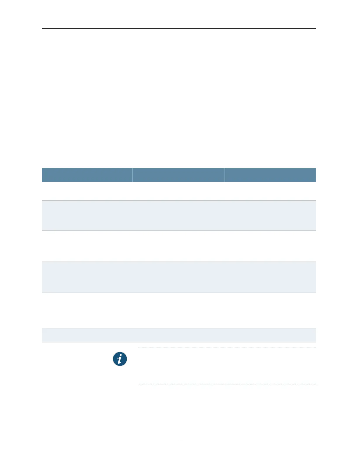
Table 38: Estimated Values for Factors Causing Link Loss
Sample (LL) Calculation ValuesEstimated Link-Loss ValueLink-Loss Factor
•
0.5 dBm
•
0 dBm
•
Multimode—0.5 dBm
•
Single mode—None
Higher-order mode losses (HOL)
•
0 dBm
•
0 dBm
•
Multimode—None, if product of
bandwidth and distance is less than
500 MHz/km
•
Single mode—None
Modal and chromatic dispersion
This example assumes 5 connectors.
Loss for 5 connectors:
(5) * (0.5 dBm) = 2.5 dBm
0.5 dBmConnector
Thisexample assumes 2 splices. Loss for
two splices:
(2) * (0.5 dBm) = 1 dBm
0.5 dBmSplice
This example assumes the link is 2 km
long. Fiber attenuation for 2 km:
•
(2 km) * (1.0 dBm/km) = 2 dBm
•
(2 km) * (0.5 dBm/km) = 1 dBm
•
Multimode—1 dBm/km
•
Single mode—0.5 dBm/km
Fiber attenuation
1 dBm1 dBmClock Recovery Module (CRM)
NOTE: For information about the actual amount of signal loss caused by
equipment and other factors, see your vendor documentation for that
equipment.
2. Calculate the (P
M
) by subtracting (LL) from (P
B
):
P
B
– LL = P
M
71Copyright © 2017, Juniper Networks, Inc.
Chapter 7: Power Specifications and Requirements
 Loading...


