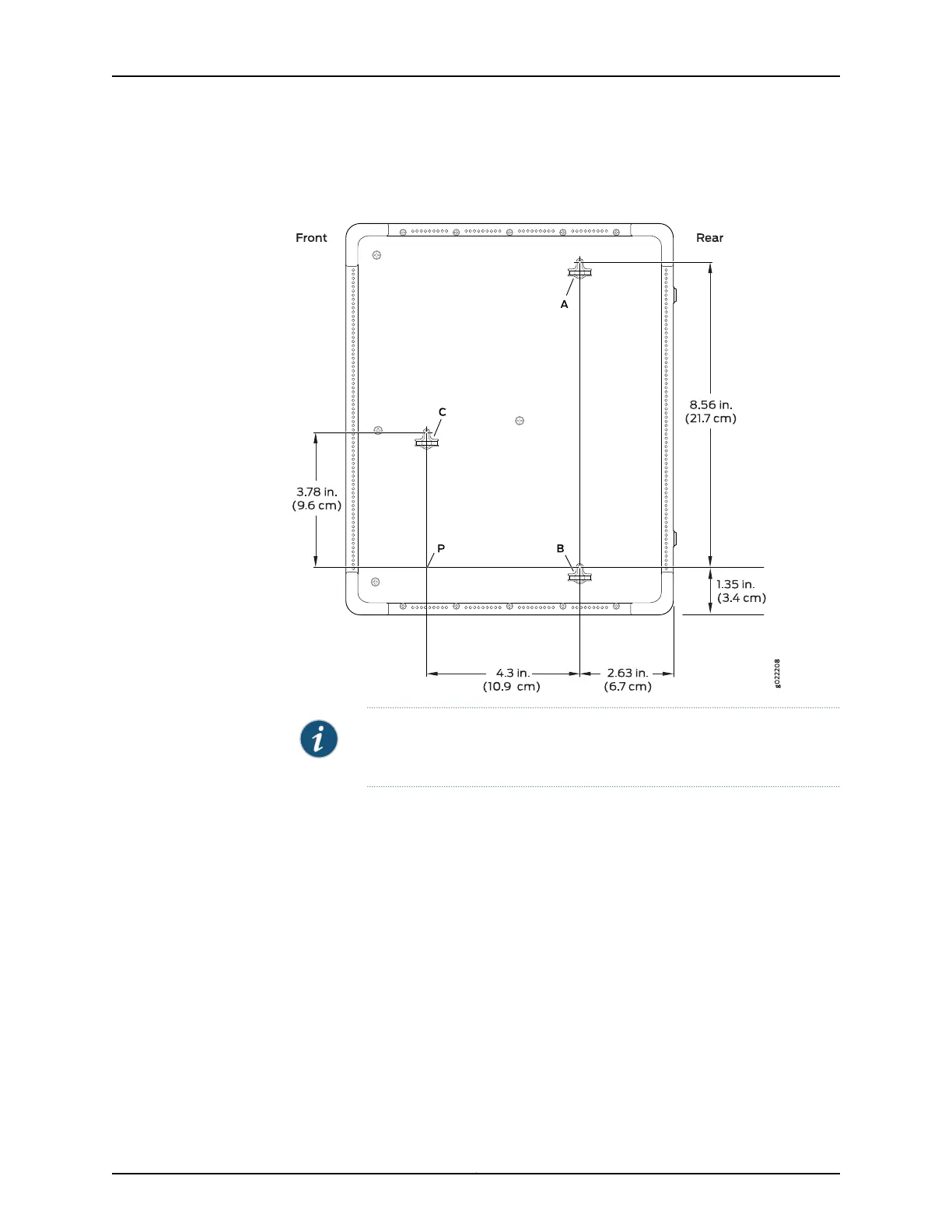
Figure 43: Measurements for Installing Mounting Screws for Mounting an
EX2300-C Switch on a Wall
NOTE: Tighten the screws only part way in, leaving about 1/4 in. (6 mm)
distance between the head of the screw and the wall.
a. Drill a hole A and install a mounting screw.
b. Drill a hole B at a distance of 8.56 in. (21.7 cm) on a plumb line from hole A and
install a mounting screw.
c. Mark a point P at a distance of 4.3 in. (10.9 cm) on a level line to the right from hole
B.
d. Drill a hole C at a distance of 3.78 in. (9.6 cm) on a level line to the top from point
P and install a mounting screw.
4. Place the switch against the wall such that the front panel of the switch faces to the
right side and the holes on the bottom panel of the switch align with the mounting
screw heads.
5. Slide the switch chassis to the left or right a bit so that the mounting screws are pushed
into the channels of the holes on the bottom panel until the switch rests firmly in place
as shown in Figure 44 on page 144.
143Copyright © 2017, Juniper Networks, Inc.
Chapter 12: Installing the Switch
 Loading...


