The front panel of EX2300 switches except the EX2300-C switch models consists of
the following components:
•
RJ-45 network ports—depending on the switch model, either of:
•
24 or 48 10/100/1000 BASE-T Gigabit Ethernet ports without PoE capability in the
EX2300-24T, EX2300-24T-DC and EX2300-48T models
•
24 or 48 10/100/1000 BASE-T Gigabit Ethernet ports with PoE/PoE+ capability in
the EX2300-24P and EX2300-48P model
•
Three chassis status LEDs
•
Four port status mode LEDs in models with PoE capability and three port status mode
LEDs in models without PoE capability
•
One Factory Reset/Mode button
•
One mini-USB console port
•
Four built-in 10-Gigabit Ethernet uplink ports. You can use these ports to forward
network traffic or configure them into VCPs to interconnect EX2300 switches into a
Virtual Chassis.
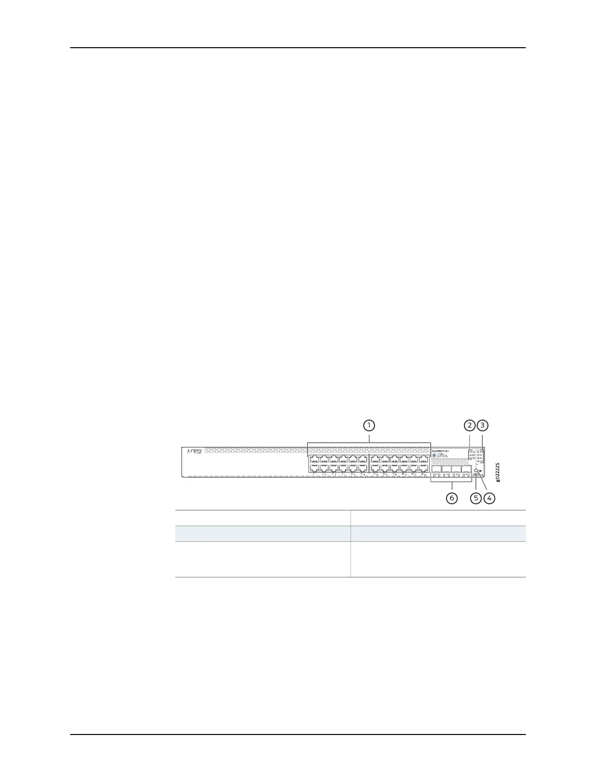
Figure 3 on page 7 shows the front panel of an EX2300 switch with 24 Gigabit Ethernet
ports with PoE capability and Figure 4 on page 8 shows the front panel of an EX2300
switch with 48 Gigabit Ethernet ports.
Figure 3: Front Panel of an EX2300 Switch with 24 Gigabit Ethernet Ports
with PoE Capability
4—1— Factory Reset/Mode buttonRJ-45 network ports
5—2— Mini-USB console portChassis status LEDs
6—3— 10-Gigabit Ethernet uplink portsPort status mode LEDs. The LED labeled
PoE is present only on models with PoE
capability.
7Copyright © 2017, Juniper Networks, Inc.
Chapter 1: System Overview
 Loading...


