CAUTION: All QFX5200 switches require two people for installaon, one person to li
the switch into place and another person to aach the switch to the rack. If you are
installing the QFX5200 switch above 60 in. (152.4 cm) from the oor, you can remove
the power supplies and fan modules to minimize the weight before aempng to install
the switch.
CAUTION: If you are mounng mulple switches on a rack, mount the switch in the
lowest posion of the rack rst. Proceed to mount the rest of the switches from the
boom to the top of the rack to minimize the risk of the rack toppling.
Four Post Installaon Procedure for QFX5200-32C or QFX5200-32C-L
To mount the QFX5200-32C or QFX5200-32C-L on four posts in a rack using the provided mounng
kit:
1. Aach the ESD grounding strap to your bare wrist and to a site ESD point.
2. Decide whether the Field Replaceable Unit (FRU) end of the switch or the port end is to be placed at
the front of the rack. Posion the switch in such a manner that the AIR IN labels on components are
next to the cold aisle and AIR OUT labels on components are next to the hot aisle.
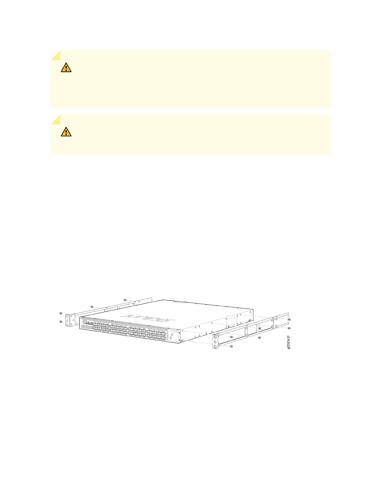
3. Align the holes in the mounng rail with the holes on the side of the chassis. See Figure 36 on page
101 to see the proper alignment for the QFX5200-32C or QFX5200-32C-L switch.
Figure 36: Aaching Mounng Rails to the QFX5200-32C or QFX5200-32C-L
4. Aach the mounng rail to the switch using the mounng screws. Tighten the screws.
5. Repeats steps 3 and 4 on the opposite side of the switch.
6. Have one person grasp both sides of the switch, li it, and posion it in the rack so that the front
bracket is aligned with the rack holes.
101
 Loading...