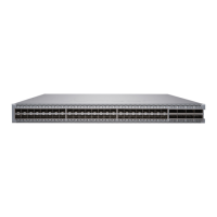
7. Have a second person secure the front of the switch to the rack using four mounng screws (and
cage nuts and washers if your rack requires them.) Tighten the screws. See Figure 37 on page 102 for
an example of connecng the mounng rails and blades to a QFX5200-32C or QFX5200-32C-L.
Figure 37: Aach QFX5200-32C or QFX5200-32C-L Switch to Rack
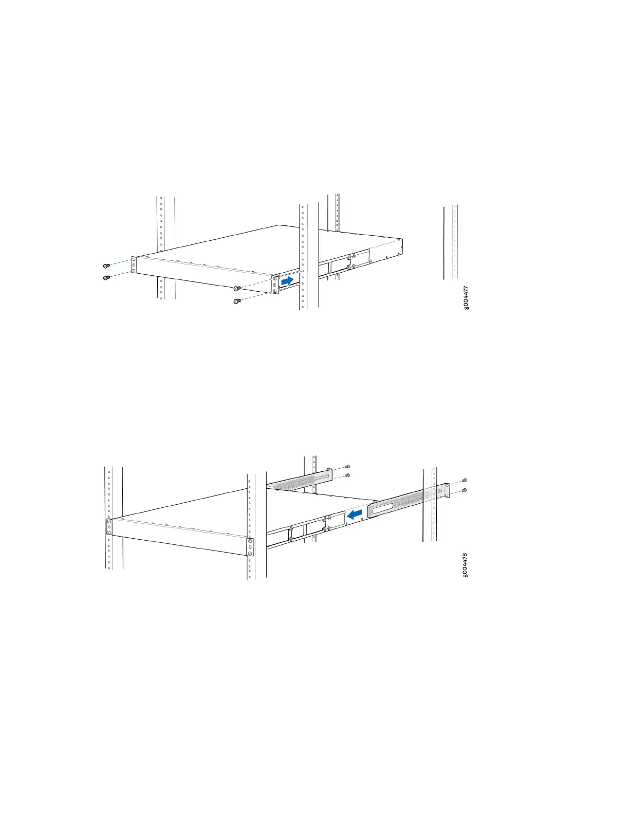
8. Connue to support the switch while sliding the rear mounng-blades into the channel of the side
mounng-rails and securing the blades to the rack. Use the four mounng screws (and cage nuts and
washers if your rack requires them) to aach each blade to the rack. Tighten the screws. See Figure
38 on page 102.
Figure 38: Slide Mounng Blade into Mounng Rail
9. Ensure that the switch chassis is level by verifying that all the screws on the front of the rack are
aligned with the screws at the back of the rack.
Four Post Installaon Procedure for QFX5200-48Y
To mount the QFX5200-48Y on four posts in a rack using the provided mounng kit:
1. Aach the ESD grounding strap to your bare wrist and to a site ESD point.
2. Place the rack in its permanent locaon, allowing adequate clearance for airow and maintenance,
and secure it to the building structure.
102
 Loading...