to provide an addional current path in a higher power chassis. Do not connect the
terminals to dierent sources.
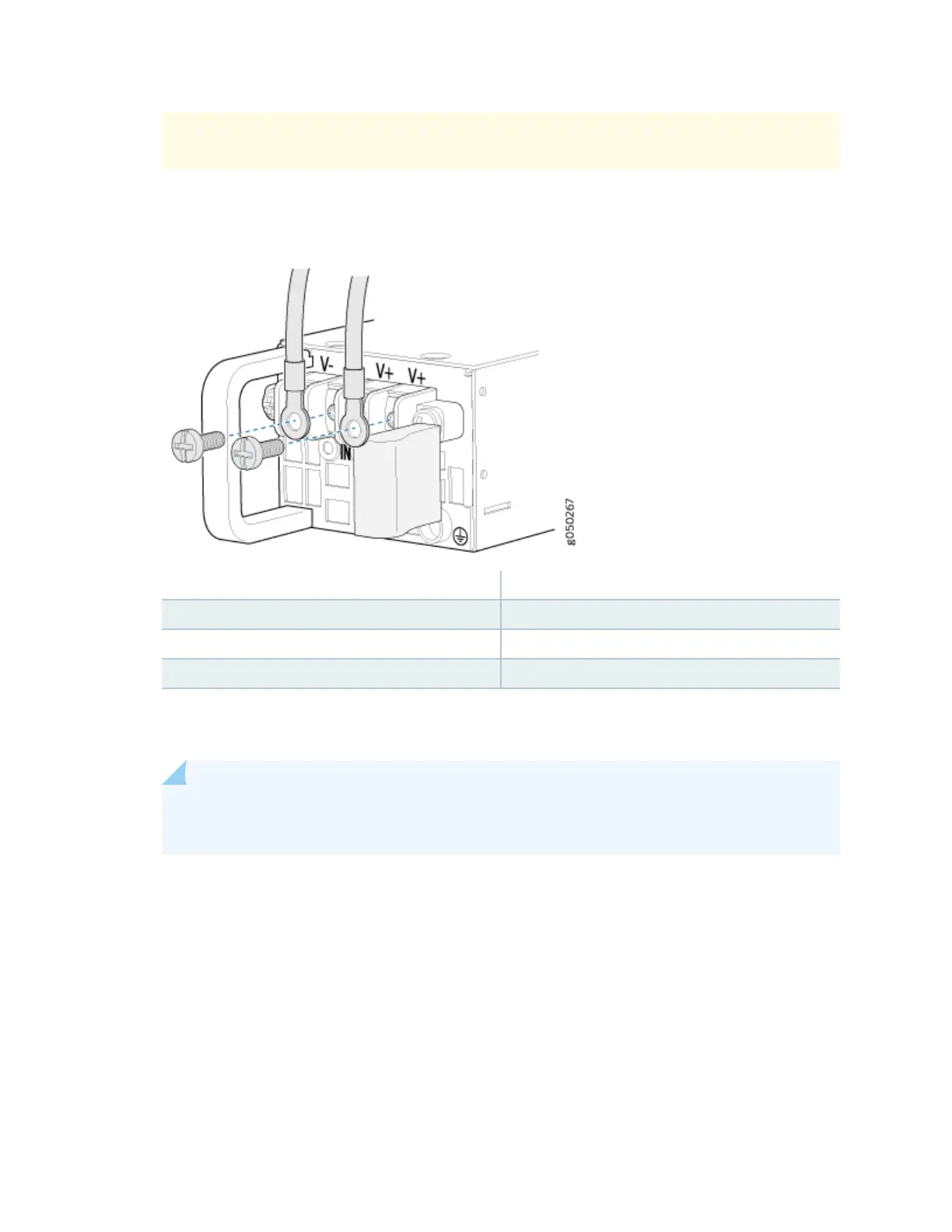
Figure 53: Securing Ring Lugs to the Terminals on the QFX5200-32C DC Power Supply
1— Shunt negave input terminals (+RTN) 5— Protecve earthing terminal
2— Shunt posive input terminals (-48V) 6— Fault LED
3— Terminal block 7— Output LED
4— Ejector lever 8— Input LED
8. Replace the terminal block cover.
9. Close the input circuit breaker.
NOTE: The switch powers on as soon as power is provided to the power supply. There is no
power switch on the device.
10. Verify that the IN and OUT LEDs on the power supply are lit green and are on steadily.
Connecng DC Power to a QFX5200-48Y
To connect DC power to a QFX5200-48Y:
1. Aach the grounding strap to your bare wrist and to a site ESD point.
2. Ensure that the input circuit breaker is open so that the voltage across the DC power source cable
leads is 0 V and that the cable leads do not become acve while you are connecng DC power.
3. Ensure that the power supplies are fully inserted in the chassis.
120
 Loading...