CHAPTER 17
Troubleshooting Components
•
Monitoring the SRX240 Services Gateway Components Using LEDs on page 107
•
Monitoring the SRX240 Services Gateway Chassis Using the CLI on page 111
•
Monitoring the SRX240 Services Gateway Using Chassis Alarm Conditions on page 113
•
Monitoring the SRX240 Services Gateway Power System on page 115
•
Loading the Rescue Configuration on the SRX240 Services Gateway on page 117
•
Changing the Reset Config Button Behavior on the SRX240 Services
Gateway on page 118
•
Juniper Networks Technical Assistance Center on page 118
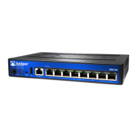
Monitoring the SRX240 Services Gateway Components Using LEDs
The LEDs on the services gateway display the status of various components.
Table 41 on page 107 describes the LEDs.
Table 41: Component LEDs on the SRX240 Services Gateway
Possible Causes and
Corrective ActionsMeaningStateLED
Normal condition. No action
is required.
The services gateway is
functioning normally.
GreenStatus LED
Normal condition. No action
is required.
•
The services gateway is
starting up.
•
The RESET CONFIG
button is pressed.
Yellow
Contact the Juniper
Networks Technical
Assistance Center (JTAC).
See “Juniper Networks
Technical Assistance
Center” on page 118.
An error is detected in the
services gateway.
Red
107Copyright © 2015, Juniper Networks, Inc.
 Loading...