5. Secure the ring lug of the -48VDC power source cable from the second DC power
source to the B– terminal.
6. Tighten the screws on the power supply terminals using the Phillips (+) screwdriver,
number 1. Do not overtighten—apply between 8 lb-in. (0.9 Nm) and 9 lb-in. (1.02
Nm) of torque to the screws.
5. Replace the terminal block cover and secure it using the screw. Use the Phillips (+)
screwdriver, number 1 to tighten the screw.
6. Close the input circuit breaker.
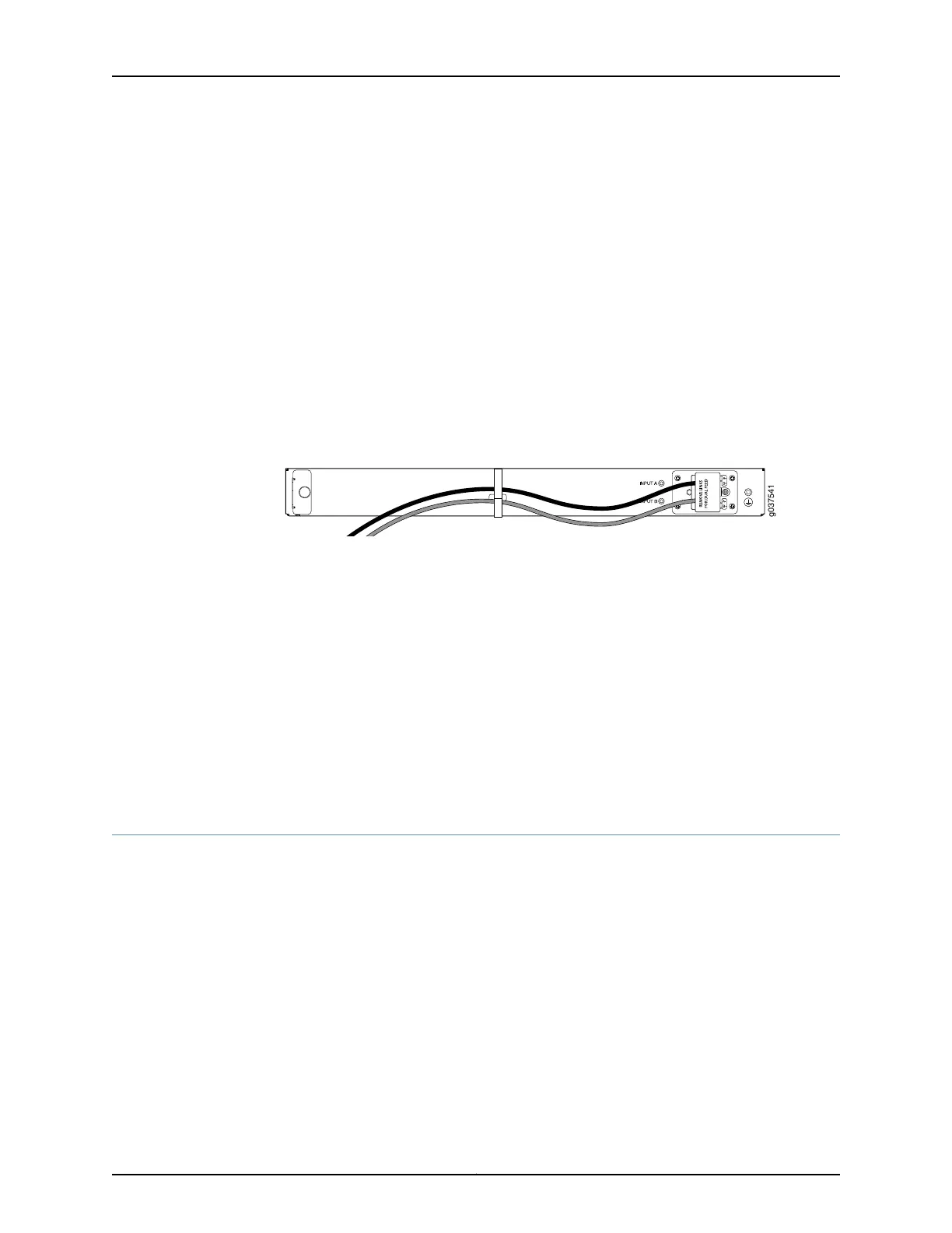
7. Verify that the power cables do not block access to router components or drape where
people can trip on them. Use the cable tie holder as shown in Figure 18 on page 74 to
secure cables so that they are not supporting their own weight as they hang to the
floor
Figure 18: Organizing the Power Cables Using a Cable Tie Holder
8. Verify that the LEDs on the power supply are lit green and are on steadily.
Related
Documentation
SRX240 Services Gateway Power Supply on page 25•
• SRX240 Services Gateway DC Power Specifications and Requirements on page 38
• SRX240 Services Gateway LEDs on page 18
• Required Tools and Parts for Installing and Maintaining the SRX240 Services Gateway
on page 48
• Grounding the SRX240 Services Gateway on page 60
• Powering On and Powering Off the SRX240 Services Gateway on page 74
Powering On and Powering Off the SRX240 Services Gateway
This topic includes the following sections:
•
Powering On the SRX240 Services Gateway on page 74
•
Powering Off the SRX240 Services Gateway on page 75
•
Resetting the SRX240 Services Gateway on page 76
Powering On the SRX240 Services Gateway
To power on the services gateway:
1. Ensure that you have connected the power supply to the services gateway.
2. Insert the plug into an AC power source receptacle (for SRX240 Services Gateway
with AC power supply, and PoE).
Copyright © 2015, Juniper Networks, Inc.74
SRX240 Services Gateway Hardware Guide
 Loading...